Is that Circ "ON"?

  • Active since 1995, Hearth.com is THE place on the internet for free information and advice about wood stoves, pellet stoves and other energy saving equipment.

    We strive to provide opinions, articles, discussions and history related to Hearth Products and in a more general sense, energy issues.

    We promote the EFFICIENT, RESPONSIBLE, CLEAN and SAFE use of all fuels, whether renewable or fossil.
Status
Not open for further replies.

jebatty

Minister of Fire
Jan 1, 2008
5,796
Northern MN
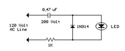
This one is a convenience, and a way to know that power is going to the circ that you wonder whether or not it is "on." How about an LED light on the circ electrical box, or a control panel, that lights up when power is "on" to the circ? Here's a circuit I picked up off the Web, wired it up today, works great. I drilled a small hole in the circ electrical hookup box to insert the LED. The rest of the components are very small and easily fit in the box. Wire it to the same wire nuts that connect the circ with power. I soldered the parts together and then wrapped everything with plastic electrical tape to prevent any inadvertent electrical short. Total cost for two of these was less then $5. The specified diode is not critical, just about any diode rectifier rated at 150 or more volts is my guess. Current draw is minimal. Radio Shack may have all the parts, or an electronic surplus store also would be good. The resistor is 1/2 watt.

April 06, 2009: Safety is really important, and if this 120 volt circuit for LED's is not adequately protected, it should not be used. See discussion on the following posts.

You can find the circuit at AC LED Circuit
 

Attachments

  • LED2.jpg
    LED2.jpg
    8.6 KB · Views: 622
Nice. I think even my mechanical engineering brain can get this one. Can't tell you how many times I've put my hand on a circ to see if it was on.

Of course, I could simply call someone who's in front of a computer and have them pull up my controller's web page, but somehow an LED is more helpful.
 
My solution to the same problem was a little more crude. I took an led outlet tester and wedged the ends under the exposed part of the wires where they enter the terminals on the pump. Leaving it dangling out I loosely replaced the cover. I've been meaning to come up with a more permanent solution. Thanks for supplying it...
 
I have done this with all of the circs in my system, as well as all of the relay outputs. At a glance, I can see what state the system is in, what is supposed to be on, and whether there is a problem with any part of it. I used LEDs on th 24 volt side too - you just need the LED and a resistor in series on the DC side.
This is especially handy for me to keep track of how often the elements in my DHW tank come on during high demand periods, as I can track the effectiveness of the sidearm.
 
My Stiebel Eltron controller has an icon that indicates when the boiler to storage circulator is on. I've had some two channel guitar amps with footswitches that didn't have LEDs, and it was kind of a pain, because when the band's pumping it can be hard to tell if you're on the desired channel by ear alone.
 
Here are two pix to show the "ON" setup. The first a close-up showing the LED glowing bright red to show the pump is "ON." The second shows the tank supply/return with the flowmeter. Return water is drawn off the bottom of the tank by means of a diptube, and supply water is fed into the top of the tank with an angle fitting inside the tank to "shoot" the hot water along the top of the tank and away from the return.

The real benefit of the flowmeter is that by measuring delta-T between tank supply/return, it is easy to accurately calculate BTUH, just for the fun of it.
 

Attachments

  • DSCN1529-1.jpg
    DSCN1529-1.jpg
    36.4 KB · Views: 431
  • DSCN1528-1.jpg
    DSCN1528-1.jpg
    20.4 KB · Views: 423
How can we take this one step further, and bring the indicator lite 100' from the boiler room to a central location in the house ? I will be installing Azel DP60 thermometers in various locations in the system and parking them at the computer area. It would be great to have the indicator light for the eko pump parked there too. Can it be done with Cat5 ethernet cable ?
 
You can put them anyplace, either 24ac or 120ac circuit, with diode/resistor/capacitor; I doubt a capacitor needed on the 24ac circuit. Wire in parallel with with control circuit that turns on the circ. The LED doesn't actually show the circ is working, only that power is going to the circ. I will test an LED on a 24ac circuit with only a resistor later today and let you know the results.
 
Adding an indicator light on the pump or at a remote location only tells you that you have power to the circulator. This doesn't really tell you if it is working or not. I have pressure gauges mounted on the output side of the pump that I can monitor to verify that the pump is running along with the LEDs mounted on my control panel. I also use the LEDs to indicate which zones are calling for heat as well. By connecting the LEDs on the open switch of the zone valve, I am sure that it is open and not just energized.
 
trehugr said:
How can we take this one step further, and bring the indicator lite 100' from the boiler room to a central location in the house ? I will be installing Azel DP60 thermometers in various locations in the system and parking them at the computer area. It would be great to have the indicator light for the eko pump parked there too. Can it be done with Cat5 ethernet cable ?

In a highly sensor-based system as it sounds as if you are pursuing, what about just putting some temp sensors on inlet and outlet of the circulator (actually, for what I am about to describe, a short distance from the circulator on inlet and outlet). If both are cold, then you know that little flow is occurring, and if the system is in a mode where the circulator is supposed to be running, then you know it's time to dig deeper and see why the circ is not pumping. If both are hot, then the circulator is operating as intended. If the inlet to the circ is hot and the outlet is less hot, then you have reason to investigate why the flow is less than it should be.
 
not to let the air out of your collective ballons, but I asked my installer/plumber how do I know if the circulators are running when we first fired it up. He gave me a little magnetic wirly gig gizmo on a key chain that said Vieesman on it. Place it on the circulator cover and it senses the motor rotation, watch :cheese: the red thing spin, simple. sweetheat
 
I will test an LED on a 24ac circuit with only a resistor later today and let you know the results.

Works just fine: red LED + 1000 ohm resister on a 24vac circuit.
 
jebatty said:
I will test an LED on a 24ac circuit with only a resistor later today and let you know the results.

Works just fine: red LED + 1000 ohm resister on a 24vac circuit.

DDDDDDDDDDDDANGERRRRRRRRRRRRRRR WILL ROBINSON!!!!

{see spaztic video from old Lost in Space TV show with robot with dryer-hose arms flailing in all directions}

if the diode or resistor fail shorted (which some such components sometimes do), you will have 120 VAC in places that you only planned/ insulated for 24 VAC

major potential for electrocution or fire hazard if you are extending this over any distance!

not worth it for signalling purposes!

[Spoken as someone who has worked with 5 VDC to 10+ kilovolts DC/ AC/ RF and has survived some pretty stupendous errors with mid/ high voltage (and still have scars in my hands to show for it); you REALLY don't want to fool with voltages above what are needed for verification purposes ....]

As the mystery critter in my swamp always (literally) says this time of year. "FFZZTT!" {I still want to know what such critter is!}
 
pybyr said:
jebatty said:
I will test an LED on a 24ac circuit with only a resistor later today and let you know the results.

Works just fine: red LED + 1000 ohm resister on a 24vac circuit.

DDDDDDDDDDDDANGERRRRRRRRRRRRRRR WILL ROBINSON!!!!

if the diode or resistor fail shorted (which some such components sometimes do), you will have 120 VAC in places that you only planned/ insulated for 24 VAC

major potential for electrocution or fire hazard if you are extending this over any distance!

You're going to have to help me through this one. If I have a 24 VAC circuit, how do I end up with 120 VAC circuit from a failing diode or resistor? I get the 24 VAC from a step-down transformer? Does the transformer have to fail too? And isn't that a risk of every 24 VAC circuit?

If you're talking about the 120 VAC circuit for the LED (resistor, capacitor, diode, LED), then I suppose you could have a point, if something failed. Isn't that one of the reasons why things are grounded? and why we have circuit breakers? ... to ground out or cut the circuit if a failure.

Almost everything I work and live with has 120 VAC somewhere. Can you give some data on resistors, capacitors or diodes failing on LED circuits? And if one fails, won't the circuit be broken? A person needs some facts to make a decision in evaluating your warning.
 
Here's another link on inexpensive neon and led indicator lights; you can select the voltage you want: Lights
 
jebatty said:
pybyr said:
jebatty said:
I will test an LED on a 24ac circuit with only a resistor later today and let you know the results.

Works just fine: red LED + 1000 ohm resister on a 24vac circuit.

DDDDDDDDDDDDANGERRRRRRRRRRRRRRR WILL ROBINSON!!!!

if the diode or resistor fail shorted (which some such components sometimes do), you will have 120 VAC in places that you only planned/ insulated for 24 VAC

major potential for electrocution or fire hazard if you are extending this over any distance!

You're going to have to help me through this one. If I have a 24 VAC circuit, how do I end up with 120 VAC circuit from a failing diode or resistor? I get the 24 VAC from a step-down transformer? Does the transformer have to fail too? And isn't that a risk of every 24 VAC circuit?

If you're talking about the 120 VAC circuit for the LED (resistor, capacitor, diode, LED), then I suppose you could have a point, if something failed. Isn't that one of the reasons why things are grounded? and why we have circuit breakers? ... to ground out or cut the circuit if a failure.

Almost everything I work and live with has 120 VAC somewhere. Can you give some data on resistors, capacitors or diodes failing on LED circuits? And if one fails, won't the circuit be broken? A person needs some facts to make a decision in evaluating your warning.

OK Jim, my bad, in that this thread's references to several different ways of setting up indicator lights had me thinking that you were referring to (or that someone might interpret it as suggesting) use of a resistor and/ or diode to run a remote LED as an indicator for a 120VAC circuit.

regarding circuit breakers, etc., yes, they're out there for protective purposes- but the current flow in an indicator circuit is unlikely to trip them- and when a circuit that depends on a dropping resistor goes "open" you've potentially got the full voltage floating around. With 24VAC that's not all that bad, but with 120 volts, it can be a bad surprise- _especially_ if someone has wired things up with wire not rated for 120VAC because they thought that they were only driving an LED through a dripping resistor.
 
In building my control system I used relays with built in LEDs. I got them from Digi-key.com

Part PB1148-ND a DPDT with LED $5.69 each. Also need the socket PB724-ND and the DIN rail ADR3515-S0700-ND rail holds six sockets.

~ Phil
 
If the resistor goes open (fuses to allow a closed circuit), would it not blow the low voltage LED and result in an open circuit? ... and/or blow the other diode and/or capacitor and also result in an open circuit? How will the circuit remain live? and if the circuit remains live, would it not short out and trip the breaker? Thanks for the input.

Safety is really importantt, and if the 120 volt circuit for LED's in my post above is not adequately protected, it should not be used.
 
jebatty said:
If the resistor goes open (fuses to allow a closed circuit), would it not blow the low voltage LED and result in an open circuit? ... and/or blow the other diode and/or capacitor and also result in an open circuit? How will the circuit remain live? and if the circuit remains live, would it not short out and trip the breaker? Thanks for the input.

Safety is really importantt, and if the 120 volt circuit for LED's in my post above is not adequately protected, it should not be used.

I think your original circuit, when (but only when) installed in the circulator's own junction box, is fine...

... the trouble would be if someone extended it using low voltage wire, as, depending on various variables, you could then see 120 volts on the remote wire not intended/ insulated for such voltages (and where someone might not be expecting it).

Also, regarding breakers, it takes a surprising amount of current to trip them. The now-standard 20 amp residential breaker will only trip if there is a sudden load well above 20 amperes, or a steady load still substantially above 20 amps. Using wire that is too small in gauge, or not rated for the voltage that it could see under some circumstances, could result in a situation where problems in a circuit end up generating dangerous arcs or other heat, fire, etc., but the breaker still might not trip, or might trip only after bad things (red hot wires....) occur for too long, because, despite the problems, the circuit is not pulling as much current as the breaker generally needs to see in order to trip. This is why the Nat'l Electric Code is pretty specific (if not easy to decipher) on minimum wire sizes in relation to breaker sizing.

Disclaimer: I am not an electrical engineer or a licensed electrician; just someone who's immersed myself in these topics since I was in elementary school, and has learned some of what I know from seeing bad things unfold when good safety practice was not followed.

And, I am not looking to throw cold water on your idea of an indicator light on a circulator- just wanted to make sure, once people started talking about "remoting" it that no one sets themselves up for hazards
 
After the years I spent in aerospace, I can't help looking at any design and thinking about failure:

1) What would the immediate effect be if this component failed?
2) How long would it likely be before anyone noticed?

If the answer to #2 is not "Immediately" then I start ask more questions:

3) What would be the long-term effect if this component failed?
4) What would be the effect if a second component also failed?

In home heating systems, the effect is generally not as dramatic as it can be on an airplane, but I still look for 'failsafe' designs where the effect of failure is no worse than degraded performace, and ideally is very noticeable.

In a hydronic system a good example would be expansion tank bladder failure. The immediate effect would be higher variation in system pressure. In most cases it wouldn't be noticed for a long time. The long-term effect would be overpressure. If the pressure relief valve also failed, the result could be explosion of the weakest component.
 
Status
Not open for further replies.