Looking for pics or descriptions of how to plump 2 500 Gal. Propane Tanks together.

  • Active since 1995, Hearth.com is THE place on the internet for free information and advice about wood stoves, pellet stoves and other energy saving equipment.

    We strive to provide opinions, articles, discussions and history related to Hearth Products and in a more general sense, energy issues.

    We promote the EFFICIENT, RESPONSIBLE, CLEAN and SAFE use of all fuels, whether renewable or fossil.
Status
Not open for further replies.

churchillrow

Member
May 21, 2008
56
Northern Nova Scotia
Hi, I'm getting ready to get some tanks delivered to my welder and I'm not sure what to get him to do. I haven't decided between primary / secondary or simplest pressurized system but am leaning towards the latter if it makes a difference.

Thanks
 
Do you have a system layout drawn up? I'm not sure how you schedule a welder without knowing what you're going to have him weld! Start with a sketch of your system....that's the first step....
 
The reason I'm rushing the tanks is that I will have access to my basement by boom truck for a short window when my house is torn apart for reno's. I don't have a system designed yet... I am waiting on heat loss calcs before I choose a boiler. When I have them which I hope will be soon I'd like to throw the boiler and the tanks down there and figure out everything else later. Is this a dumb approach? Can I take from you previous reply Stee that system design would affect how the tanks are plumbed?

Thanks again
 
I went with 3 in the top, middle and bottom.(all 1-1/4") Only the nipples on the tanks are 1-1/4 but the manifold is 1-1/2. Works pretty good at keeping the tanks stratified all the way to the bottom. My top tank is 330 and the bottom 1000.
 

Attachments

  • IMG_1739.jpg
    IMG_1739.jpg
    30.2 KB · Views: 1,888
  • IMG_1740.jpg
    IMG_1740.jpg
    39.2 KB · Views: 5,083
  • IMG_1612.jpg
    IMG_1612.jpg
    35.9 KB · Views: 1,904
There is no such thing as too many connections.

I am using one 500 gallon tank, here are the connections for it:
1 1/2 on left used for return, a 36" nipple is married to the bushing. The nipple goes to the bottom of the tank, the end is plugged and 8- 1/2" holes are drilled radially,
1 1/4 bushing welded into gage hole used for the 1" boiler hot water input
1 1/4 bushing married to a 4" long nipple to be used for the pickup (any air bubbles will be above the nipple)
1/8 npt tapped for an air separator

All of my "special" parts are screwed in so they can be removed and replaced. I did not put any connections in the bottom, my circulator pump is below the tank elevation.

004-10.jpg
 
How many tanks, and what sizes are they?

How do you plan to install them? Side by side? Stacked on a rack? Horizontal, or standing on end?

If you can figure this out, then a lot of the tank setup for fittings and such becomes fairly "standard" regardless of how the rest of the plumbing hooks up, because the tanks are pretty much doing the same thing no matter how your system is designed...

In your situation, I would say to make sure that you have it so that you can get water in the bottoms of the tanks and out the tops (or vice versa), preferably with as little turbulence and mixing as possible.

If you are going to be stacking the tanks, put in a few pairs of connections so that you can tie them together with as short and straight a hookup as possible, ideally in several places - i.e. ports in the top of one tank and the bottom of the other. (In effect making them one big tank)

Ideally make the ports bigger than you plan to use, as you can always bush them down, but you can't make them bigger.

If I was doing something, and had a willing welder (and possibly a large budget) I'd probably try putting a fitting in one or possibly each end of the tank near the top and bottom (If stacking near the top of the upper tank and the bottom of the lower one) that would let me run a pipe along the top and bottom of the tank interior so that I could drill a bunch of holes in it and use it as a diffuser....

Another item that could be a wonderful thing for some plumbing setups is if your tank had a "manway" style port that you could optionally use as a way to insert HX coils into the tank - something that can't be done in most cases with a pressured tank, and that is IMHO the biggest single drawback to a pressure tank...

BTW, just from a future proofing standpoint, will you still be able to get a tank in and out of the house when your renovations are finished? Tanks should last a long time, but someday they WILL leak and need replacing...

Gooserider
 
Lots of info....
Gooserider: The 2 tanks I am using are 500 gal, 9.5 ft long and 36" in diameter so I should be able to get replacement tanks into the basement. I would like to stack them horizontally one atop another on pallet racks or the like. The diffuser idea seems good but if it is to expensive or impractical can I put a diffusing "nipple" into the bottom of the bottom tanks and the top of the top tank? Can you give me an idea situations where a HX would be useful in a pressurized system? How Big is a big port, 1.5" ??

Steve:
"1 1/4 bushing married to a 4” long nipple to be used for the pickup (any air bubbles will be above the nipple)
1/8 npt tapped for an air separator"

Pardon my ignorance but what is the "pickup"
And what is an air separator?

Ulook: You say you are getting good stratification. Do you have diffusers or just nipples in the tanks.

Thanks for the pics and ideas
 
Repeat info on stratification in a horizontal tank, 39" diameter, 19' feet long, 1000 gal. Return from a diptube about 4" off the bottom, and 1/3 from one end of the tank, using an existing fitting. Supply using an existing fitting with a 90* bend inside the tank to inject hot water horizontally along the inside top of the tank in a direction opposite from the diptube, also about 1/3 form the end and about 1' from the diptube. Stratification is intense and tank heats very evenly, top to bottom. Example: top of tank may be 160F and bottom of tank (if start from "cold") easily could be 90F. Bottom of tank will stay 90F until whole tank is heated, then bottom of tank temp rises fairly rapidly as whole tank above is hot.
 
churchillrow said:
Lots of info....
Gooserider: The 2 tanks I am using are 500 gal, 9.5 ft long and 36" in diameter so I should be able to get replacement tanks into the basement. I would like to stack them horizontally one atop another on pallet racks or the like. The diffuser idea seems good but if it is to expensive or impractical can I put a diffusing "nipple" into the bottom of the bottom tanks and the top of the top tank? Can you give me an idea situations where a HX would be useful in a pressurized system? How Big is a big port, 1.5" ??
You can use a diffusing nipple, or whatever else you can make work - the basic idea is that you want to move the water in and out of the tanks with as little mixing as you can manage so as to keep as much stratification as possible.

The idea of using an HX is pretty much any case where you need to transfer the heat to another system, and can't use the boiler water directly for whatever reason... Possibilities might include preheating for DHW, a glycol loop to feed a garage heater, swimming pool heaters, solar systems, etc... All of these can be handled with sidearm or flat plate exchangers, but this takes extra plumbing, and can require more pumps. OTOH, an in tank coil is very simple and direct, adds no moving parts, or other such complications... With a non pressurized tank, it is easy to add as many coils as one wants, but it is difficult with a pressurized tank unless one has a "manway" in which case you have some way to slide a coil into the tank and either hook it up to fittings in the tank wall, or possibly in the manway lid itself...

Big port is sort of an ambiguous term, I would probably say the simplest definition is at least 1-2 sizes bigger than the pipe you are thinking of hooking up. Fittings and bushings get more expensive as the size goes up, but you gain in the ability to slide more things into the tank like dip tubes and diffusers, etc... I haven't seriously priced welding stuff into tanks, but from what I've heard, the costs for the fittings to get welded into the tank are such a tiny part of the cost as to be almost irrelevant, and that there isn't a lot of difference in the welder's labor fee for a big fitting vs. a little one, as both involve about the same amount of setup and prep. Talk to the welder, but I'd almost be inclined to go for 2-3" ports just for the flexibility.

[/quote]Steve:
"1 1/4 bushing married to a 4” long nipple to be used for the pickup (any air bubbles will be above the nipple)
1/8 npt tapped for an air separator"

Pardon my ignorance but what is the "pickup"
And what is an air separator?

Ulook: You say you are getting good stratification. Do you have diffusers or just nipples in the tanks.

Thanks for the pics and ideas[/quote]
Not to speak for Steve, but my guess is that by "pickup" he is meaning the outlet for the tank, or the point where the hot water goes in and out.

An air separator can be used to refer to several different items, but generally is a vent type device used to purge air trapped in the system.

Gooserider
 
Gooserider
Thanks for your always thoughtful suggestions, I am going to try to come up with what I am actually going to do and I will post here after I've talked to the welder.
 
Just nipples. Before putting the insulation on and having 160* water entering the tanks, you could put your hand on the side of the tank and it would be cold....move your hand up just a few inches and it would be hot. (the same distance all the way across the tank.)
 
Yes, the 4" nipple means that the water that leave the tank/reservoir comes from just below the top of the tank, keeps the trapped air or floating junk from getting sent to the loads. This is a very important part and it makes getting the system up and running possible. Without it the first large bubble that reaches the pick-up will move to the circulation pump and stop the pumping.

The air separator (sometimes called an air vent is a TACO 400-3) has a cap that you open to allow it to operate. Air can exit through the cap but as the water rises in the device it will push a float up and close the valve inside, hence trapped air is bled out but not the water.

I have two married parts which are 1" diameter nipples welded to bushings. The bushing threads into the tank. The four inch is a pickup, the 36" is a return. The 8 -1/2 holds drilled radially exceeds the area of the 1" pipe (the pipe end is closed so that all of the water is sent horizontally to minimize agitation. My loads are low so my flow rate is not that high.

The other tank pics had three boiler to storage tank input ports that might be nice to have.
 
Any pipe that needed to be welded in place I used heavy wall or schedule 80. This doesn't include the 1/2" black used for sensors. On upper tank the 2" nipple just goes in and is flush with top of tank and makes a 90 and reduces to 1.5". The bottom nipple is 36" X 2" and goes almost to bottom of tank. I welded a piece of flat stock to the end of this to act as a diffuser so water is pushed to bottom of tank. The way that pipe goes into tank it's at an odd angle, it looked like the incoming water would push up the side of the tank causing mixing. I used a dip tube on the side for easier access for threading and to keep pipe off the floor, but the pipe is inside the sides of the 2 tanks, out of harms way. I add a support frame after tanks were slid into place for extra stability, and to take some of the weight off the legs of the lower tank. After the tanks are insulated the frame will give me a place to attach some sheet rock / fire retardant material. I have had success with a 100G propane tank for the expansion tank for the system.
 

Attachments

  • Tanks installed.jpg
    Tanks installed.jpg
    46.4 KB · Views: 1,491
  • Support Frame.jpg
    Support Frame.jpg
    19.1 KB · Views: 1,281
Something that is worth considering in any hydronic install is a hot water filter on the hot water line leaving storage and supplying the system; also on the boiler return line. I use a 50 micron filter on mine, although I just picked up a case of 100 micron filters off of ebay at a buck a piece. Besides filtering any crap in the lines, when you change the filter you get a pretty accurate read of your water condition from the color of the filter. Any brown or reddish color indicates rust/corrosion somewhere and likely indicates you need an increase in alkalinity.
 
Steve-- Smart with the air stuff.

Rob -- I take it that your 1/2" sensor pipe is welded on to the surface. Also I didn't follow about the dip tube.... I think I am going to try to find used pallet racking to hold the tanks as I have no welding skills.

Jim -- Filters sound good....

Interesting how many little details people come up with to refine their installs. Maybe when this thread seems dead I'll compile them all and make one last post,

Thanks Again
 
The idea of diffusers or in my case a 2" pipe and a flap is to slow down the water movement into / out of tanks to prevent the mixing of the water inside the tank. You want to increase stratification by reducing turbulence. Hot water in and out on top and cooler water in and out the bottom. I knew where I wanted to put in my lower dip tube but when I slid the pipe in the hole, in the tank, I saw there was a problem. I wasn't coming in at 90 degrees and the water was going to shoot up the side and start the water in the tank spinning, reducing stratification. Another fix would have been to drill holes in the side of the pipe and cap the end. Or you could weld right to bottom of tank.
Yes, I welded the 1/2 in black to the sides. They seem to work nicely with rapid temp changes. I'm going to cut them back closer to the tanks once the insulation is on.
My side supports were to achieve a couple of things. My tanks are in a high traffic area.
They are for added stability.
To add support to the lower tanks legs.
You are now asking those legs to support more than 2X what they were use to. I don't know what they are rated for nor do I want to find out.
I also added some supports, short legs between tanks. I wanted to keep any weight off the 4" welded pipe tank connectors.
You mentioned pallet racks. Check the ratings. Don't know where your located but there is a place in Walpole, MA that sells them used.
Rob
 

Attachments

  • tank drawing0001.jpg
    tank drawing0001.jpg
    32.8 KB · Views: 1,221
jebatty said:
Repeat info on stratification in a horizontal tank, 39" diameter, 19' feet long, 1000 gal. Return from a diptube about 4" off the bottom, and 1/3 from one end of the tank, using an existing fitting. Supply using an existing fitting with a 90* bend inside the tank to inject hot water horizontally along the inside top of the tank in a direction opposite from the diptube, also about 1/3 form the end and about 1' from the diptube. Stratification is intense and tank heats very evenly, top to bottom. Example: top of tank may be 160F and bottom of tank (if start from "cold") easily could be 90F. Bottom of tank will stay 90F until whole tank is heated, then bottom of tank temp rises fairly rapidly as whole tank above is hot.

Jim, it sounds like you are using plain pipe (no diffusing with holes, etc.)?

Is anyone using a primary/secondary with pressurized storage. I like the concept but I don't see how the storage could operate with only 1 circ & loop back to the primary. Steve J asks the question in the P/S sticky but the answer he gets suggests that it is not necessary since the tank will be mixed together anytime the boiler is producing heat. Everyone in this thread seems to indicate the tank staying stratified while boiler is operating either with diffusing holes or locating "pickup" and "returns" properly. I would think you could use 1 circ & 1 loop if you added 2 3way valves near the circ to reverse the direction of flow but I have not seen that discussed anywhere. The cost of 2 3way valve is probably about the same as adding a 2nd circ with a loop I suppose. The "switchover" process would probably overly complicate things as well. Those with P/S how is your storage plumbed?

SteveJ said:
So, there should be two circuits into the butffer tank:

1. As drawn in the diagram, to charge the tank from the primary loop.
2. (Not shown in diagram) Circulator reversed from that in diagram with a short dip tube, to extract heat from the tank to the primary loop.

Correct?

Then what is the general rule for sizing the primary circulator in relation to the secondary circulators?

Thanks,
Steve

master of sparks said:
Sure, you could have two loops into the buffer. What I find is any time my boiler exceeds 150 the buffer circ is running. As such the tank is always blended, not much stratification with the buffer tank circ running.

On one hand I want the cooler water from the bottom of the tank to return to the primary loop and boiler to leverage delta t to the boiler and keep the efficiency up.

However if the tank stratifies, for instance over night without the buffer circ running, in that case you would want to pull any heat loads off the top, warmest point. My buffer circ runs until that tank drops to 100F as my radiant floors can use temperature that low.

If you have loads thay require higher temperatures, of course shut down the buffer at the lowest possible "useable" temperature.

Whenever the buffer circ is off the boiler output would be going directly to the loads without "seeing" the buffer.

Keep in mind under "ideal" conditions, at load, the boiler would be matched exactly to the load and the buffer becomes "unknown" to the system. The buffer is merely a parking space, either for excess btus, over heat protection, maybe solar storage input.

You might consider the buffer as a "fixer" for the in-ability of solid fueled appliances to track close or exactly to the load. Different jobs require different size tanks to try to "nail" the perfect blend of not storing anymore then really needed, but enough to buffer all conditions, or perhaps offer some "non burn" times

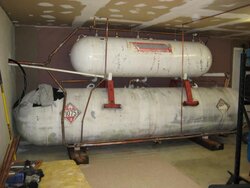
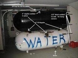
I can't say there is an ideal piping, size, or control configuration. It really needs to be sized and designed to the task you have in mind. I chose 500 gallons because it will buy me a days worth of heat, at design. It fit in the space nicely, and I don't mind switching to a mod con LP boiler back up.

Others here want to burn hard and long and store more "time." For them more capacity may be better.

Keep in mind more capacity = more standby loss. I feel there is an upper limit to realistic thermal storage, but it's a moving target :)

Th primary loop circ is usually a low head, high GPM circ. It's ONLY lob it to move fluid around that circulator loop. It doesn't move any flow through secondary loops. Either the Grundfos 15-58 or Taco oo7 on speed 1 will usually be fine for that. To move 150,000 BTU at a 20Fdegree delta T you need to move 15 gpm. look for a circ to do that job at a low head, some of the DHW recirc pumps are great, but expensive as they are usually bronze or stainless volutes.

hr
 
huskers said:
I would think you could use 1 circ & 1 loop if you added 2 3way valves near the circ to reverse the direction of flow but I have not seen that discussed anywhere. The cost of 2 3way valve is probably about the same as adding a 2nd circ with a loop I suppose. The "switchover" process would probably overly complicate things as well. Those with P/S how is your storage plumbed?


Thus diagram shows the use of a 4-way valve to provide correct flow direction to and from storage.
 

Attachments

  • temp.jpg
    temp.jpg
    85 KB · Views: 1,886
Don L, what is the box above the storage circ do? I can't quite make out what the name says. You have three separate physical locations to deal with.
 
huskers said:
Don L, what is the box above the storage circ do? I can't quite make out what the name says. You have three separate physical locations to deal with.


It is a controller for the pump to move water in and out of the storage tank. It is made by Steca. The controller has two senors. One monitors tank temperature and the other monitors available supple temperature. Basically if supply temperature is greater than tank temperature the pump will be activated. The Steca controller is normally used in a Solar application. I will be building a NFCS controller in the near future and it will be used to replace the Steca.

Yes I have three different locations to deal with. It makes the project more complex and challenging. Also more fun.
 
This is great! I have one 250 gallon tank for this year that I'm hooking up next week and plan to add a second on top of it next year. I love this site!
 
Highjack alert.

Wow.... No wonder you need an NFCS Don! I thought I had a lot of pumps. :cheese:
That is a nice looking diagram, do you mind if I ask what you used to create it?

Kris
 
kabbott said:
Highjack alert.

Wow.... No wonder you need an NFCS Don! I thought I had a lot of pumps. :cheese:
That is a nice looking diagram, do you mind if I ask what you used to create it?

Kris

I use Visio for the drawings.

Yes there are a lot of pumps, but they are all 007 or 15-58 so they use little power. Right now I use several NoFossil inspired 12 volt relay boxes to control the pumps. The relay boxes are currently controlled by a series of relays, thermostats and aquastats that form the brains of the system. I surprised myself on how will it is working. The NFCS will be the icing on the cake so to speak. With it I intend to replace the Steca controller and the Techmar controller used for cold water protection, plus allowing me to really fine tune the overall system. This stuff is terribly addictive. NoFossil should put out a warning on his web site!
 
Don L said:
huskers said:
I would think you could use 1 circ & 1 loop if you added 2 3way valves near the circ to reverse the direction of flow but I have not seen that discussed anywhere. The cost of 2 3way valve is probably about the same as adding a 2nd circ with a loop I suppose. The "switchover" process would probably overly complicate things as well. Those with P/S how is your storage plumbed?


Thus diagram shows the use of a 4-way valve to provide correct flow direction to and from storage.

Very nice diagram Don, the only thing I might suggest on it is that it looks to me like it would be better if you pulled the heat for the storage tanks off before the heat for the floor... I would think that even though the floor might only pull a small amount of water, it is going to return cooler, and thus cool the water in the line going to the storage tanks... If you pulled the tank water off first, you'd be getting the hottest possible water into the tank, and could use the cooler water in the floor, which has a lower temp requirement anyway...

Gooserider
 
Status
Not open for further replies.