I've been shopping for tanks for pressurized storage for my EKO 40 install... shooting for 500-1000 gallons total. Whatever I get needs to fit through a 35" opening into my basement (which has a 7' ceiling), so that has been somewhat limiting.
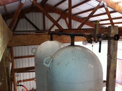
I recently got a lead on some tanks nearby that are ~265 gallons (1000L?) and were used to transport some type of alcohol for industrial processing. They came from Europe and have two 3/4" British pipe thread holes at one end, each of which connects to a dip tube that goes about half way across the tanks as depicted below. The guy says the tanks were held horizontal and they would blow nitrogen in the top to purge the alcohol out the bottom. These tanks are attractive because they fit in the door, can fit standing up, are reasonably priced and very clean.
I considered buying two and racking them horizontally with pallet racking, similar to this setup. This would let me use the existing ports/dip tubes, however not sure 3/4" would cut it... 137,000 / 500 x 20 = 13.7 gpm and max gpm for 3/4" is only 6.5, so two tanks wouldn't cut it. I could add a third but that would be some odd racking, or a fourth for symmetry but now that's a lot of fittings, connections, flow to equalize, etc...
What seems better would be to get three of these tanks, abandon the existing ports and have someone weld up new fittings. I like the layout from the Effecta Lambda brochure, depicted below. Seems like it simplifies controls too... EKO charges storage, circs draw from storage. I'm eyeing up Floydian's constant circulation/iValve/ODR setup but haven't seen anyone use this with baseboard yet.
The Effecta tanks sure have a lot of tappings... some are for electric backup elements so I can forgo those. How does it work when you're drawing heat from the tanks? How do you draw heat equally from all three, or do those three horizontal connections between the tanks equalize the temps between them?