Pellet Stove Operation Explanation!

  • Active since 1995, Hearth.com is THE place on the internet for free information and advice about wood stoves, pellet stoves and other energy saving equipment.

    We strive to provide opinions, articles, discussions and history related to Hearth Products and in a more general sense, energy issues.

    We promote the EFFICIENT, RESPONSIBLE, CLEAN and SAFE use of all fuels, whether renewable or fossil.
Status
Not open for further replies.

yomoto

New Member
Mar 18, 2010
6
Ireland
Hi All, I'm attempting to build a pellet stove as a university engineering project on possibly trying to improve efficiency in pellet burning systems. The only problem is I am at the start of this task and know little to nothing about pellet stoves. I know theoretically how they work. What I would like to know is can anyone give me a very simple description of what the electronic control systems control? and in what order. i.e. when the power is switched on 1. The fan comes on to create negative pressure in the combustion chamber? What are the startup / shutdown sequences usually? etc, etc.

Also please could you explain what are the major control components, Augers, pressure switches, fans, pcb's and any manufacturers of the same. Not the stove manufacturers but the actual motor and fan manufacturers etc. Any help would be much appreciated.

I would just like to learn as much as I can as quickly as I can!!

We have some ideas from a combustion point of view to increase efficiency but need to know more about the actual stoves.

Thanks
 
Make a stove that has a large auger with a strong auger motor/mounting bracket that wont crap out the first time it meets a long and/or hard pellet.
So, anyway, I'll do my part and let the fellow forum goers fill in what I forgot and correct what I said wrong

1. Hit the start button (if this is a stove that does not have electronic ignition, drop a cup of pellets in the pot and light with gelled alchohol, then hit the start button)
2. Combustion fan will start up and the system will go thru a series of checks for vacuum and in some cases to monitor that no hopper lids or stove panels are open. If all safetys check out, combustion fan should continue. The feed auger may or may not start upon the initial firing of the stove
3. The firebox heats up to the point it triggers a thermo snap disk which tells the auger it's ok to feed pellets in cases where this is delayed.
4. Auger feeds pellets into a basket with holes in it (on the majority of typical combustion stoves) and the combustion fan either blows or pulls air thru the holes creating a small, hot fire.
5. When temps in the heat exchanger reach a certain temp, the convection fan will kick on blowing heat into the room.
 
6. Insert a safety in the power line to the auger motor of the form of a normally closed manual reset thermo disc on the heat exchanger that activates below the ignition temperature of the pellets and within a safe range for the output convection air. This will open when the set temperature is reached the circuit will open and shut the auger off stopping the pellets from entering the burn pot. The stove will run out of fuel and eventually the proof of fire thermo disc or heat sensor will indicate no fire and the controller can shut the combustion fan off.
 
There are a number of blower and blower motor manufactures, the blowers (depending upon manufacturer) run on either AC or DC from 12 volts to 115 volts. They are generally fractional horsepower shaded pole (although not all are) who's speed is controlled by pulse width modulation or an equivalent, these motors may or may not be thermally protected.

The controller is responsible for generating the required combustion and convection fan speed control steps, there is also on some stoves a trim control for this function to properly match the motor to its electrical environment.

7. Insert a safety in the form of an electrical control circuity that prevents the convection fan from being turned off or run at a speed that fails to remove the heat from the heat exchanger at the firing rate set by the heat control.
 
The auger is timed in one of several ways and the feed rate is tied to the combustion fan speed.

The two common forms are fixed cycle where the auger on time and off time sum to a fixed cycle time and the variable on time fixed off time or fixed feed time variable off time that doesn't sum to a fixed time cycle.

There are several feed systems in use as far as augers are concerned, some stoves use a horizontal auger system and some use a diagonally mounted auger with a drop chute on the end.

The horizontal auger systems come in both single and double auger systems.
 
The chap behind the Europa has a very good handle on combustion efficiency I suspect that'll you'll have to really try to out do him. Most pellet stoves are very good at burning the fuel, where they have problems is in the use of electricity to run the system and the efficiency of the heat exchanger (the heat exchanger issue is complicated by the ash that gets deposited on all interior surfaces of the stove including the heat exchanger).
 
Dayton and FASCO make a lot of the combustion and convection fans and motors. There are at least two companies I'm aware of that make auger motors I'll leave that as an exercise for the student engineer. Ah, back in the day when the big thing was to design a bridge as part of one of your engineering classes.
 
A O Smith is another blower manu! Better quality IMO than fasco. Watch the Dayton motors. They are not shaded pole. They are PSC and are very hard to reduce speeds and they don't recommend that anyway! Just FYI!
 
Gee Jay, I think I was kind enough to warn the OP that there were differences all over the place.

We can't exactly spoon feed all of the information.
 
Seems to me that the real project here would be to devise a way in which the stove could maintain efficiency for extended periods of time via self-cleaning mechanisms. Over time the ash build up decreases airflow and insulates the heat exchangers. Mechanisms to monitor, control or eliminate ash build up would be the next great invention.
 
Too LARGE...will be 2 Part/Posts

Came across this trolling the internet:

<begin c&p>


Control Board Functions

Product models covered: BrandX AC & DC units
Topic: This technical bulletin will be addressing how the control board operates, what it
initiates, the difference between the AC and the DC board, manual mode, T-stat mode,
diagnostics, voltages, and how the control board and other electrical parts work together to make
the unit operate.
The AC and DC control boards primarily function the same way, except the DC board
has to function on 12 volts of power. It is imperative that the voltage power supply is constant
and the board has the consistent voltage for each operation. If the voltage is not consistent every
time, it will not allow the blowers to operate properly. Throughout this bulletin, information will
be listed pertaining to AC or DC. Each function of the circuit board will be explained to give a
clear picture of how each operation has to work. When appropriate page numbers will be
referred, in the owner’s manual, to avoid duplication of effort. The owner’s manual gives a good
insight on how the board needs to operate. When the power is plugged in to the unit or circuit
board, the board goes through a self diagnostic check, which tests all circuits to make sure that
everything is operating correctly. If any of the safety features are tripped like: low limit sensor
thermostat, high limit sensor thermostat, open circuits or closed circuits that are not supposed to
be, a light will blink in the heat level bar to indicate what is wrong. If the #3 heat setting light
blinks, it means that the proof of fire (low limit 110 deg. Thermostat located on the exhaust
blower) is not operating properly (read page 30 of the owners manual). If the #2 heat setting
light blinks, it means that the vacuum switch has tripped and the circuit is open. Once power is
plugged in and the board has gone through its self diagnostics, the board is ready for operation.
When the ON/OFF button is pushed, it will initiate the startup cycle, (read page 29, circuit board
functions), the draft/exhaust blower starts up (full voltage), and the timed cycle begins.
Startup cycle: When the board’s ON/OFF button is pushed and the draft blower kicks in, a
timed cycle is initiated. The cycle has a minimum time of 8 minutes and a maximum time of 15
minutes. During this time the proof of fire snap disk (110 deg. normally open) has to engage or
the board will go into a shut down cycle. Also, the vacuum sensor circuit must be closed or the
board will go into a shut down cycle (the auger motor will not turn while the switch is open).
The room fan will not run unless the proof of fire snap disk is closed. During the startup cycle
the board automatically will run a startup feed rate, (Room fan voltage AC= line voltage, DC=
12 volts) (Draft blower voltage AC= line voltage, DC= 12 volts). This will be the startup feed
rate for the auger motor no matter what mode that the board is in. This feed rate will run until the
proof of fire snap disk thermostat closes or the board goes past the 15 minute startup cycle and
shuts down. If the proof of fire snap disk closes before the 8 minute minimum startup time, the
feed rate will stay at the start up feed rate until the 8 minute minimum, then it will go to

whatever feed rate has been selected (1-5) The feed rate is selected by pushing the heat level
button once for each heat setting. The heat level button will function 30 seconds after the
ON/OFF button is pushed. The ON/OFF light will blink during the start up cycle until the proof
of fire snap disk is closed, the 8 minute minimum has passed, or the 15 minute total cycle has
passed, then the light will stay lit solid green. After 30 seconds of start up time has passed, the
auger button can be pushed and held to bypass the timed auger cycle and the auger will run
continuous as long as the button is pushed. When the button is released, the auger will go back
to the start up timed cycle. If the board is in the “manual” mode setting, all start up cycle
operations will function. If the board is in the “T-stat” mode the board will go through the start
up functions even if the wall thermostat is not calling for heat. When the 15 minute cycle is
completed the board will go to whatever heat setting the manual or T-stat mode dictates. If the
board is in the “auto” mode, the wall thermostat has to be calling for heat for the start up cycle to
initiate.
 
Part 2

Control Board Functions...continued...

When the ON/OFF button is pushed, the igniter function will initiate. On the DC board,
the igniter function will not initiate if the unit is on battery power. When the igniter function
initiates there is a 30 second delay before power is applied to the circuit. Then full line voltage is
applied to the igniter circuit for 10 minutes. If the vacuum circuit is opened during the first 8
minutes of the start up cycle (someone opens the door and then closes it), and the board ON/OFF
button is pressed to re-start, the igniter function will start over. If the igniter shorts out so that
there is an open circuit, or the igniter option is not used so the wires are left not plugged into an
igniter, the rest of the board functions will still operate. If the proof of fire switch is in the closed
position and the vacuum sensor opens (someone has opened the door), causing the operator to
reset the board, the igniter will run for only 5 minutes and then shut off. When the proof of fire
snap disk closes, the room fan circuit will be initiated with full line voltage on the start up cycle.
If the proof of fire circuit closes between the 8 minute minimum and the 15 minute maximum
start up time, the room fan will go to whatever voltage that the heat setting dictates. The room
fan receives full voltage on all heat settings except #1.
The draft/exhaust blower runs from the time that the ON/OFF button is pushed. It will
run on full line voltage all the way through the start up cycle. If the proof of fire fan circuit
closes between the 8 minute minimum and the 15 minute maximum start up time, the draft
blower will go to whatever voltage that the heat setting dictates. If the proof of fire snap disk
does not close during the 15 minute maximum start up cycle, the auger will stop running, the
igniter will have stopped running after the 10 minute igniter time, the room fan will not be
running because the proof of fire snap disk did not close and the board will shut off. When the
15 minute start up cycle has completed and if the proof of fire snap disk has not closed, the board
shuts down, the #3 heat level light will blink until the ON/OFF button is pushed and held for 5
seconds to re-set the board, the draft blower will run for an additional 15 minutes and then shut
off. During the start up cycle, if the vacuum switch is tripped (the circuit opens) the board will
go into a shut down cycle and the #2 heat level light will blink. During the start up cycle and any
time that the vacuum switch circuit is opened, the functions of the board will not be interrupted
until after 15 seconds. If the vacuum circuit closes during the 15 seconds, the board ON/OFF
button will not have to be pushed to re-set the board. If the vacuum circuit closes after the 15
seconds, the board ON/OFF button will have to be pressed for 5 seconds to re-set the board and
resume functions.
<end c&p>
 
BLIMP said:
http://www.google.com/patents?id=2xEJAAAAEBAJ&printsec=abstract&zoom=4&dq=6,336,449#v=onepage&q=&f=false Europa gassifier for pellets allows 10/1 stochiometry.

There is also a patented Combex system stove which uses 1 fan for both exhausting & pressurizing the incoming combustion air. I think a pressurized stove would deliver more heat through the stoveshell.

POOK??? is that you?
 
jtakeman said:
BLIMP said:
http://www.google.com/patents?id=2xEJAAAAEBAJ&printsec=abstract&zoom=4&dq=6,336,449#v=onepage&q=&f=false Europa gassifier for pellets allows 10/1 stochiometry.

There is also a patented Combex system stove which uses 1 fan for both exhausting & pressurizing the incoming combustion air. I think a pressurized stove would deliver more heat through the stoveshell.

POOK??? is that you?
can't be.
grammer is too good.
 
BLIMP said:
http://www.google.com/patents?id=2xEJAAAAEBAJ&printsec=abstract&zoom=4&dq=6,336,449#v=onepage&q=&f=false Europa gassifier for pellets allows 10/1 stochiometry.

There is also a patented Combex system stove which uses 1 fan for both exhausting & pressurizing the incoming combustion air. I think a pressurized stove would deliver more heat through the stoveshell.

I believe that the Europa's burn system has been improved since that patent was granted. I'm sure that Franks can fill the current information. I took a serious look at that stove, but there were no dealers in Maine when I went to get a stove. As much as I don't mind tinkering with a stove, I don't plan on doing the warranty work on one when it has "issues". So I'll stick with my multinational box of chocolates with the Canadian builders plate on it made with parts from at least 7 other countries.

The Combex system supposedly provides a more consistent air flow through the burn pot and thus can lead to a more consistent burn in the presence of minor air path issues.
 
yomoto said:
Hi All, I'm attempting to build a pellet stove as a university engineering project on possibly trying to improve efficiency in pellet burning systems. The only problem is I am at the start of this task and know little to nothing about pellet stoves. I know theoretically how they work. What I would like to know is can anyone give me a very simple description of what the electronic control systems control? and in what order. i.e. when the power is switched on 1. The fan comes on to create negative pressure in the combustion chamber? What are the startup / shutdown sequences usually? etc, etc.

Also please could you explain what are the major control components, Augers, pressure switches, fans, pcb's and any manufacturers of the same. Not the stove manufacturers but the actual motor and fan manufacturers etc. Any help would be much appreciated.

I would just like to learn as much as I can as quickly as I can!!

We have some ideas from a combustion point of view to increase efficiency but need to know more about the actual stoves.

Thanks

Here's some Links to some key components...I have much more...will be forth coming. ;)

Augers Motors

Draft Inducers aka Combustion Fans

More Draft Inducers

Convection Blower Assembly

Economical Controller

Even more Economical Controller
 
AUTOMATIC FEATURES
A. THERMOSTAT OPTION:
When using a thermostat, set the stove to one of the medium or higher settings. The stove will
burn at the rate selected on demand by the thermostat (medium to high).
When the room temperature drops below the thermostat setting, the thermostat switch will
close, allowing the stove to operate at the medium or higher settings. When the room
temperature matches the thermostat setting, the thermostat switch will open, allowing the stove
to operate at the low setting.
B. THERMOSTAT EQUIPMENT REQUIRED (optional): A low voltage millivolt
thermostat that will automatically switch between settings previously selected.
Type CL2 thermostat wire-20 AWG, 2 conductors.
C. STOVE PRESSURE SENSOR:
A blocked flue, a down draft, open door, open hopper lid, negative or positive pressure in the
home, drafty location of the appliance, not hooking up the outside air, improper venting or
failure to clean the 3” exhaust in the stove will cause the pressure switch to shut off the fuel
feed. To resume operation, it is necessary to locate the cause and correct it. Restart the stove
following the instructions in this manual.
D. HIGH TEMP THERMODISK:
If the stove overheats, it will shut itself down safely. The stove may not be restarted until it
has cooled and the reset button is depressed. (See Thermodisk location section) If the auger
does not turn after cleaning the back of the unit, you might have tripped this disk. Check it by
pressing in on the center button until it clicks into place.
E. SELF-IGNITER:
Automatically ignites the pellets within 3-5 minutes, without the use of fire starter. The igniter
will continue to run for approximately 10 minutes until a fire is established. If the fuel is wet,
poor quality or the hopper not primed, it might take 2-3 cycles for the unit to properly light.
Using a little fire starter will help with this.
F. PROOF OF FIRE THERMODISK:
If the temperature required by the PROOF OF FIRE thermodisk is not high enough within the
10 (15 minutes on the AC models) minute cycle, the auger will stop feeding pellets. The proof
of fire and cool down sensor are combined into one 110 degree auto reset thermo disk.
G. COOL DOWN SENSOR:
After the power switch has been moved to the “OFF” position, the blowers will continue to run
for approximately 45 minutes. The cool down sensor will allow the stove to cool down and
then automatically shut itself off. If the hopper runs out of pellets and the stove cools off, the
auger will stop feeding. However, the blowers will continue to run until the power switch has
been moved to the “OFF” position.


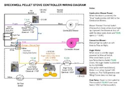
Here's a simple wiring diagram that covers all the basics required:
 

Attachments

  • wiring.jpg
    wiring.jpg
    85.6 KB · Views: 1,332
As an engineer I will give this tid bit of advice.

KEEP IT SIMPLE

A pellet stove does not need to be complicated to work well and keep its owner warm.

The more electronics you add to the thing the sooner it will develop troubles.

Simple industrial grade adjustable on off timers do a wonderful job of controlling the feed motor.

A room air fan with a speed control and a snap switch that will overide and speed the blower to high speed at a given temp is a good design.

The draft inducers (Exhaust fan) in many cases use a triac setup to vary the speed in relation to the fuel feed.

All these varying electronic add ons just makes failure more likely.


Major parts

Cabinet to house the mechanical workings and the fire pot.

Feed motor and auger system
Room air fan
Draft fan (exhaust fan)
Draft control device (damper/ regulator)

Make ash removal easy. Make the airflow path through the stove such that excess flyash collects in predetermined cleanout areas that are easy to reach.

Keep the end user in mind when it comes to maintenance and operation.


These things dont need to require a PHD to run. This is little more than a glorified camp fire.

The additions of the following safeties are a must.

Low temp snap siwtch to keep the auger stopped if there is no heat at the exhaust outlet

High temp snap switch to stop the fire if it gets too hot.

vacuum switch to close the circuit to the feed motor when there is a slight neg pressure in the firebox.
Pressure switch that will open if the exhaust becomes plugged ( very low water column pressure.

The vacuum switch will stop the stove if the door is opened or the draft fan quits.


The controls need to provide the user with the ability to change the heat output and to control the room blower speed.

The auger feed needs to be set up so that the usual on time of the auger is fixed and the off time (time the thing is left to burn) is variable by the user.

The start button that has been spoken of is a simple one shot timer that bypasses the low temp snap switch until the stove has fire and the low temp switch closes (15 minutes or so/adjustable at setup)

Trimmer controls for setup are a good plus.

Keep in mind

Make the thing easy to use. Keep it safe so the end user wont hurt himself (unless he/she is an absolute idiot)

Design in enough safeties that the stove will, if any failure occurs, simply shut off.

In todays world of the micro electronic BONANZA it has become so popular to bolt a computer onto everything.

A pellet stove does not need an excessive amount of electronics to make it work and work well.


The more complex you make the design the more HATE MAIL you will recieve.

I owned an older pellet stove (1990 model) and ran it for 17 years of trouble free service.

The controls were as simple as dirt and it had plenty of safety devices to protect the end user.

Concentrate on a good airflow through the fire pot and through the heat exchanger.

HINTS
A replaceable aluminum heat exchanger setup is a lovely perk.

Outside air connections are a must but you might consider a device that in the event of a power failure would close and prevent the backflow of smoke into the room.

Pellet stoves are quite nice in that they can be direct vented with a short horizontal run and not need a long toturous chimney system to vent.

This said the incidence of a backflow with a power outage is always possible.

Hint

If you make your design so the exhaust is at the top or top rear then there is some natural draft to .

Hint

Sheet metal of up to 3/16 thick is great for he firebox proper and then much lighter materials for the bulk of the mechanical cabinet and the hopper.

HINT
Make the hopper such that the pellets/fuel can easily roll down to the auger entrance.

Avoid "Bottom feeders" burnbacks can happen and cause hopper fires

Develop a good airwash system that shoots a column of air across the viewing windows to keep them clean.

Do this in such a way as to prevent any openings to the room such as many companies have done.

Hint

Design a door latch that is PET proof
A playful dog left at home alone can and has bumped door handles resulting in the door being set ajar.

This is also the reason for a pot pressure sensor.


Just some thoughts to get you off and rolling

Good luck and please keep us posted

Snowy
 
If I understand, the OP's primary task is to end up with a stove w/ better combustion efficiency.

Now with that said, to get this accomplished in a timely fashion one would think
the student would require procurement of "off the shelf" readily available components, so the student's
emphasis remains on the primary task. "Plug N Play", if you will, for everything else.

Of course we all have our own idea of the "perfect stove" but that doesn't appear to be the mission here.

I apologize if my take on this is incorrect. :)
 
"I’m attempting to build a pellet stove as a university engineering project on possibly trying to improve efficiency in pellet burning systems."

The OP didn't restrict the task to just combustion efficiency, s/he believes s/he has very good ideas on the combustion end of the project , s/he is looking for sources for various parts and a basic idea of how it goes together from an operational standpoint. IE the sequences of actions that take place.

Gleason Avery makes auger motors as does Rotom and Merkle-Korff.

Snowy gave several very good hints about keeping things simple and safe.

A major problem the OP is going to run into is making everything work together.

As Jay has all ready mentioned and I have alluded to that even something as simple as a blower (or blower assembly) can make you pause.
 
I think you just said...what I just said...What's your point?

Or maybe you just didn't understand my point???
 
MOS
You are right on the mark. Use off the shelf technology and parts.

This concept has many ways of returning benefits to both the original manufacture and the end user.

The manufacture saves a bunch on building costs. The engineering can still be very sound but does not force the manufacture to source custom made components.

The end user can repair the thing in a pinch without having to wait for a shipment from the dealer or ????

If the manufacture is bought up as is the common trend these days, by big companies like Lennox and then the line up scrapped, the stove does not become a parts orphan.

Most of the needed components are readily available in the industrial market place.

Strive to make a user friendly piece of equipment that is efficient as well as easy to operate and care for.

Avoid high end electronics that can and will fail at the least opportune time.

Make your cabinet design esthetically pleasing so it can fit in with a wide variety of home furnishings and not stick out like a pimple on a ducks Butt.

Keep the controls down right stupid simple.

OHHHH I would love to be involved with this project.

Snowy sits grinning
 
SmokeyTheBear said:
Most pellet stoves are very good at burning the fuel, where they have problems is in the use of electricity to run the system and the efficiency of the heat exchanger (the heat exchanger issue is complicated by the ash that gets deposited on all interior surfaces of the stove including the heat exchanger).

This seems like it could be a real simple mechanism to scrape the heat exchanger on a time. Heck even a manual item would be great on my harman, can't believe the do not have these on the stoves, I nkow they do on the Harman furnaces.
 
Status
Not open for further replies.