Pipe diagram, final draft

  • Active since 1995, Hearth.com is THE place on the internet for free information and advice about wood stoves, pellet stoves and other energy saving equipment.

    We strive to provide opinions, articles, discussions and history related to Hearth Products and in a more general sense, energy issues.

    We promote the EFFICIENT, RESPONSIBLE, CLEAN and SAFE use of all fuels, whether renewable or fossil.
Status
Not open for further replies.

emesine

Member
Apr 24, 2009
185
Indiana
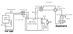
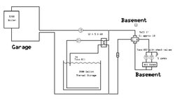
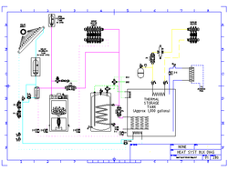
Here is an updated diagram, much simplier than previous designs. What do you think?

I put a variable speed pump at the boiler. It will slow down if the boiler temp drops down below 150 in order to give the boiler some time to catch up and get up to temperature. VS pumps are expensive, but not as expensive as a standard pump and a big mixing valve for boiler protection.

This is an in-floor radiant system, so I should be fine even when storage temperatures drop down below about 110. I used a mixing valve with a Cv of 9.3 in order to get enough hot water injection when my storage temp is very low. If storage is 110, water to the system will be 100F (10F drop across the heat exchanger). Assuming there is a 10F delta across the heating zones, this will still yield 93,000 BTU per hour to heat the house. If my storage is 180F, I will have 418,000 BTU available to heat the house (!!!). Any problems here?

DHW will be a problem when the storage is below about 130, so I am not relying on wood to fully heat my DHW. I am just using the storage tank to pre-heat the DHW. If anyone can think of a better system, I am all ears.

Thanks for your help!

Andrew
 

Attachments

  • diagram.jpg
    diagram.jpg
    31.3 KB · Views: 830
I guess you know your pump sizes, the main loop, boiler must be a lot bigger than mine.

I don't suppose it makes sense to put in a storage tank bypass?

Why not build two more copper immersion heat exchangers and remove the two heat exchanges and pumps?

Move your load pumps to the suction side, they can then run cooler.
 
Andrew, just a quick comment you can ignore if you already have it figured.

Is that driveway heat coming directly off the boiler supply a snow melt setup?

I realize this is a schematic diagram and all the details are not shown but I know of a homemade snow melt application that had to be manually valve controlled down to a trickle so as not to suck all the heat out of the boiler and leave nothing for the house. And depending on how sophisticated (as in more money) the controls are the return temps from snow melt can be about 32F. That could refrigerate your tank and turn your boiler into a water fountain. It's hard to over estimate how much heat snow melt can take. And that's about all I know about it.
 
Steve,

I need about 20 gpm at about 10 feet of head. A 011 would be perfect, but I haven't seen one of those in a variable speed form. I'm still looking. I'd love to do a storage tank bypass, but I don't exactly know how to put it in the plan.

I would love to use copper immersion heat exchangers, but I think the heat exchange would require so much copper as to make it cost prohibitive. First off, the copper immersion would have to take about 20 gpm. Second off, it would take an awful lot of copper to effectively transfer 175000 BTU. I don't really know how to calculate it. Do you have any idea how large it would have to be?

As to the driveway heat (I'm going to stub it in for now), I will make sure my storage tank is hot before doing the driveway. It will cool the storage down considerably, but that tank will hold 2.2 million BTU, enough to do my driveway without cooling the house too much!

Andrew
 
I'm sure you already have, but just in case you haven't, don't forget to look at the performace curves on the Taco 00R. Its about a $100 less than some of the bigger variable speed pumps from various makers and a little work horse too. I questioned it on paper as well, but now I'm in love.
 
Not sure the best way to figure the copper immersion heat exchangers, but from what I've seen of the prices on flat plates, you can stuff an awful lot of copper into the tank for the cost of two flat plate HX's... I'm not sure of the math, but I would expect that a set of several 50-100' coils of 1/2" tube in parallel would give plenty of transfer and low flow resistance, and with the proper pump setup you can use the same HX to both charge the tank and draw from it to heat the house by swapping the loads...

For the DHW, I'd consider looking at NoFo's trick of using two mix valves in sequence to use less of the heated water from your DHW tank, and put a pump on the DHW preheat coil as an extra zone that would fire any time the storage tank was hotter than the DHW tank. I assume that's an electric tank, and you could then have the electric kick in if the super heat didn't keep things hot enough.

Gooserider
 
Goose,

I spent 3 months trying to work out a single heat exchanger design. Basically, it will work just fine..... but causes several problems that end up costing more than the extra heat exchanger. To start with you need a zone valve on the boiler loop. The best I could do on that one was a solenoid at $400- (that's about the price of the second HX) It also complicates the mixing valve setup- a 4 way won't work due to dynamic pressure changes over the exchanger, so I would have to install two 3 way valves to get enough Cv. That adds at least an extra 100 or two, not counting the $$$ to pay my installer. If you have a simple design, I am all ears. I have yet to see a good design for unpressurized storage.

Does anyone know how to calculate heat exchange over a copper coil?

As to DHW, I will look into that. I am just learning about Delta T thermostats.

Thanks!
 
I am not following the reason for dual flat plate ex, However if you must do it this way give some thought to keeping the storage from mixing otherwise you will
HAVE to get the whole tank hot before you can get any heat. I would go P/S or hydraulic separator and ditch the second flat plate. Heat exchangers are one of
the more inefficient parts of these systems and having to go through two just doubles the loss.
 
Well what I've seen done is the "back to back pump" approach, where one uses two pumps facing in opposite directions, and wired so that only one can ever run at a time... One pump is near the boiler and pushes water into the house loops and storage tank coil. It runs as long as the wood boiler is hot, and can have a flow check in it. The second pump is between the house loop and the tank and runs when heating from storage. It pulls water out of the tank coil, and sends it towards the house loop and the boiler, but the flow check in the boiler pump keeps it out of the boiler loop. The gas boiler loop has its own pump and flow check, and bypasses both the wood boiler and storage tank....

This puts one big coil in the storage tank for the heating system, plus added smaller coils for the DHW and driveway loops (I would put the driveway loop pulling from storage, not the boiler, plus that loop needs to be glycol filled, so it should have a separate HX and expansion tank - you DON'T want to have to run the entire system on glycol!) Simple, no zone valve on the boiler loop, no extra mixing valves on the heating loop needed. Gets rid of the two flat plates, and I think two pumps...

Gooserider
 
AAARRRGGGHHH.....

Just when I think I'm done..... they draw me back in.

Thanks, Goose. I really appreciate your input. I attached what I think you're describing. Two problems:

1. The storage will get the first heat. It might be hours before the house sees heat once the boiler pump starts firing. On reflection, the temp drop over the HX will only be 20F. If the boiler is at it's minimum of 140F, the house is still getting 120F. Not an issue.

2. Both the house and the boiler are running through the HX in the same direction. the problem here is that it will be very hard to stratify the tank- The pump will pull water from the bottom and dump it on the top both when storing heat and heating the house. This is a significant problem- don't know how to fix that one. It would be less of a problem (but still an issue) using a copper coil HX. Again, I'm just not sure if I can get enough heat transfer with a copper coil.

Otherwise I love it.

Andrew
 

Attachments

  • alt5.jpg
    alt5.jpg
    27.7 KB · Views: 535
Sorry, but what you are drawing isn't quite what I was describing... :red:

I'm attaching a first draft of what I'm wanting to do in our house if we ever get the finances and so forth together. I describe a lot more in detail in my "Systemic Dreaming" thread, but pay special attention to P3 and P4, and ignore the solar and pool loops.

If the boiler is running then P3 (which should have a flow check that isn't shown) is on, feeding heat to the house zones, the DHW tank, and the storage coil, pushing through non-running P4.

If the boiler is not running, then P3 is off, and the flow check blocks flow through the boiler, and P4 comes on to feed any house or DHW demands, pulling through the storage coil in the opposite direction. No flat plates involved at all, and since one is pulling through the coil in opposite directions, stratification should be preserved fairly well.

The loop for the garage heater is intended as a glycol loop, so it's isolated from the rest of the system - it could do your snowmelt loop instead.

The DHW section shows NoFo's double mix valve setup - any demand for DHW first pulls the makeup water to the DHW tank and the first mix valve through the coil in the storage tank. If the storage tank is hot enough, you won't actually get much, if any water out of the DHW tank itself, if not you get a blend, but the preheat of the makeup will stretch the DHW tank supply. If the water from the first mix valve is still to hot, which is likely if the tanks are hot, then the second mix valve gives you the final 120*F max output.

Hope this helps....

Gooserider
 

Attachments

  • heat_syst_block_diag-1.png
    heat_syst_block_diag-1.png
    7.4 KB · Views: 562
Status
Not open for further replies.