Proposed Piping for Eko

  • Active since 1995, Hearth.com is THE place on the internet for free information and advice about wood stoves, pellet stoves and other energy saving equipment.

    We strive to provide opinions, articles, discussions and history related to Hearth Products and in a more general sense, energy issues.

    We promote the EFFICIENT, RESPONSIBLE, CLEAN and SAFE use of all fuels, whether renewable or fossil.
Status
Not open for further replies.

huffdawg

Minister of Fire
Oct 3, 2009
1,457
British Columbia Canada
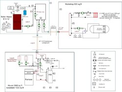
Hi folks, I have redrawn my piping for my Eko 40. I have been looking over master of Sparks sticky and tried to get it as close to his primary secondary diagram as I could.

Of course I have a few questions.

1) will it work

2) will the alpa circ pump work as boiler protection.

3) I am not sure about sizing the alpha pump , Is there only one size ?

I will also be plumbing in extra close spaced tees for storage and a oveheat loop for later use.


the primary loop would be close to 100' of 1-1/4 pex except the piping close to the boiler which will be black iron.
I will be shutting off the GB while running the EKO 40. All the load pumps will be powered except the GB boiler pump and dhw pump.


thanx huff
 

Attachments

  • DSC_0158.jpg
    DSC_0158.jpg
    135.4 KB · Views: 728
I'm having a difficult time getting your drawing to work in my head. I am confused on the way you show the closely spaced tee's. The way you have shown them simply won't work in my estimation. As well, the loop where heat is drawn off for in floor heat and baseboard heat has no pump! Maybe I'm looking at this wrong, but I think the plan needs further clarification.

Don
 
Close. Those closely spaced tee "cross overs" need circs in them. The EKO is fine, it has a circ to flow, I'd run that on a 150F on control, sensor at the top of the boiler.

Then a circ in the bridge between the EKO "loop" and the primary loop.

Why not tie the GB, I assume a Buderus GB boiler?? into the loop with a set of closely spaced tees. Also the DHW tank into the primary loop.

Think of that primary loop as a transmission. The EKO and GB are engines to put power (thermal power) into the loop. Everything else is a power take off from the loop. So every set of tees needs a circ to move flow through the attached load.

The sticky at the top of the forum has a good start. You have more going on but the principle is the same. Here is one drawing from the article link below.

Go to this link for a good read on your proposed system.

www.hpacmag.mercuryemail.com/archives/2009/3_April.pdf


hr
 

Attachments

  • Picture 53.png
    Picture 53.png
    48.8 KB · Views: 672
in hot water said:
Close. Those closely spaced tee "cross overs" need circs in them. The EKO is fine, it has a circ to flow, I'd run that on a 150F on control, sensor at the top of the boiler.

Then a circ in the bridge between the EKO "loop" and the primary loop.

Why not tie the GB, I assume a Buderus GB boiler?? into the loop with a set of closely spaced tees. Also the DHW tank into the primary loop.

Think of that primary loop as a transmission. The EKO and GB are engines to put power (thermal power) into the loop. Everything else is a power take off from the loop. So every set of tees needs a circ to move flow through the attached load.

The sticky at the top of the forum has a good start. You have more going on but the principle is the same. Here is one drawing from the article link below.

Go to this link for a good read on your proposed system.

www.hpacmag.mercuryemail.com/archives/2009/3_April.pdf

Ok will move the alpha to the bridge, will I still need the danfoss on the boiler loop if im using an alpha pump on the primary loop?


How would you tie the gb boiler into the loop? I will post an actual pic. of the gb boiler.


hr
 
Here is a picture of my Primary loop. The left side is where Supply comes from Storage or Boiler, closely spaced "T". I run 4 Zones currently, Zone 1 = DHW, Zone 2 first floor, Zone 3 = 2nd floor, Zone 4= Hot tub and then a stubbed in Zone for future expansion.

Hope this helps more then a diagram.
 

Attachments

  • Primary loop.jpg
    Primary loop.jpg
    112.2 KB · Views: 593
The GB injects, with the Buderus pump station, into your distribution. It would be nice to tie in above the pump station, below the boiler. That way you could cover then DHW which tees off above the Buderus pump station. I don't see that there is enough pipe length to tie in there, however. That pump module was built to close couple to save space. It would take a major repipe to connect into the system in the best spot.

You could tee the wood boiler interface to the distribution loop with closely spaced tees. But that would not allow you to get to the DHW load with the wood boiler, without flowing the GB without firing the burner.

You are trying to make two ends meet in the middle, and use that panel as it is built. This will take some thinking to arrive at a workable solution. If it were me I would start from scratch, but there is some time and money invested in the piping you show.

hr
 
in hot water said:
The GB injects, with the Buderus pump station, into your distribution. It would be nice to tie in above the pump station, below the boiler. That way you could cover then DHW which tees off above the Buderus pump station. I don't see that there is enough pipe length to tie in there, however. That pump module was built to close couple to save space. It would take a major repipe to connect into the system in the best spot.

You could tee the wood boiler interface to the distribution loop with closely spaced tees. But that would not allow you to get to the DHW load with the wood boiler, without flowing the GB without firing the burner.

You are trying to make two ends meet in the middle, and use that panel as it is built. This will take some thinking to arrive at a workable solution. If it were me I would start from scratch, but there is some time and money invested in the piping you show.

hr

I could probobly lift the gas boiler roughly 6" that might give me enough room to install closely spaced tees with the smallest amount of repiping.
 
timberr said:
Here is a picture of my Primary loop. The left side is where Supply comes from Storage or Boiler, closely spaced "T". I run 4 Zones currently, Zone 1 = DHW, Zone 2 first floor, Zone 3 = 2nd floor, Zone 4= Hot tub and then a stubbed in Zone for future expansion.

Hope this helps more then a diagram.

looks more simple than what I have going. nice.
 
RobC said:
Huffdawg, Did you see this post ? Could that be a workable solution rather than doing primary / secondary ? Less electronics / controls too.
https://www.hearth.com/econtent/index.php/forums/viewthread/66601/

Yes I have read through that post. Looks pretty slick. Im not sure if it would be suitable for my setup or not. My eko and (future storage) are in the back of my detached shop about 50' away from my gas boiler system.

As far as the design end of my system im pretty green at. but putting it all together after I get an approved method from the guys on this sight will be the easy part. Its just getting something workable with my existing system that is the hard part.

And I would like to say thanx for everyones input on this site . Its a great help :)
 
Don L said:
I'm having a difficult time getting your drawing to work in my head. I am confused on the way you show the closely spaced tee's. The way you have shown them simply won't work in my estimation. As well, the loop where heat is drawn off for in floor heat and baseboard heat has no pump! Maybe I'm looking at this wrong, but I think the plan needs further clarification.

Don

Hi Don merry Xmas and all the best in the New Year. I was looking at the diagram for your system and noticed your primary loop pump is not on the bridge from your boiler circ loop.
I understand why on the gas boiler end on my drawing but I am confused about the primary loop pump after looking at your schematic.

Cheers huff
 
huffdawg said:
Don L said:
I'm having a difficult time getting your drawing to work in my head. I am confused on the way you show the closely spaced tee's. The way you have shown them simply won't work in my estimation. As well, the loop where heat is drawn off for in floor heat and baseboard heat has no pump! Maybe I'm looking at this wrong, but I think the plan needs further clarification.

Don

Hi Don merry Xmas and all the best in the New Year. I was looking at the diagram for your system and noticed your primary loop pump is not on the bridge from your boiler circ loop.
I understand why on the gas boiler end on my drawing but I am confused about the primary loop pump after looking at your schematic.

Cheers huff


You may be looking at an older schematic of my set up. I have made some changes and eliminated the 4-way valve. What I have now is very similar to your drawing with a boiler loop connected to the primary loop. My boiler loop is connected to the primary loop using closely spaced tees. I am not sure how you plan to connect your boiler loop to your primary loop. I found your diagram showing that connection a bit confusing. It did not look like closely spaced tees to me, so I was not sure.

I would use closely spaced tees for your connection between the boiler loop and the Primary loop. For primary/secondary piping that is the best way to go in my opinion. I monitor the boiler return temperature and based on that control the circulator on the Primary loop to control return temps to the boiler. Right now I just turn the primary circulator on/off to do this, but I plan on eventually controlling the speed of that circulator for better performance.

As well, on your diagram it appears to me that the circulator pumping into the GB will just cycle water through that that boiler in a short loop. The water coming out appears to be pumped right back in to me.

Best of the season to you and all as well!

Don
 
Huff, Attached is an updated drawing of my system. Lots of Primary/secondary with closely spaced tees.

Don
 

Attachments

  • springbrook boiler.jpg
    springbrook boiler.jpg
    84.8 KB · Views: 417
Don L -- What did you draw this on?? I have the taco program - not much luck with it. would like to figure it out because it has inputs. Any one else got a program they like. I don't have auto cad or the skills for that matter.
 
bigburner said:
Don L -- What did you draw this on?? I have the taco program - not much luck with it. would like to figure it out because it has inputs. Any one else got a program they like. I don't have auto cad or the skills for that matter.

I use Microsoft Visio.
 
Status
Not open for further replies.