Questioning Old Schools of Thought: Pumping Away From the Expansion Tank

  • Active since 1995, Hearth.com is THE place on the internet for free information and advice about wood stoves, pellet stoves and other energy saving equipment.

    We strive to provide opinions, articles, discussions and history related to Hearth Products and in a more general sense, energy issues.

    We promote the EFFICIENT, RESPONSIBLE, CLEAN and SAFE use of all fuels, whether renewable or fossil.
Status
Not open for further replies.

slowzuki

Minister of Fire
I know this is an old heating concept, a B&G;rep repopularized it in the 60's I hear. I've never heard the whole reasoning. I sat down and drew a little sketch and the lowest pressure in the system always occurs at the pump suction unless I have a a high elevation somewhere else in the system.

I can see the fill point will raise the "base" system pressure if the pressure at its connection point drops below its static fill during operation due to the delta P across the pump.

The best reason I see to pump away from the bladder tank is placing it at the point of lowest pressure in the system (pump inlet) allows it to be slightly smaller and will reduce the "base" system pressure if the fill valve is left on the supply side of the boiler.

Please someone try to explain to me why this old timey tradition stands in small residential systems! I don't see it saving money or helping system functioning.

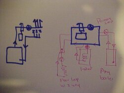
Why I'm even looking? My water inlet for the boiler is low, and I want to pump up into it so I'll never airlock my pump. The air scoop and float valve need to go on a high area of the system which for me is the boiler outlet leading to the storage tank. My air scoop is made to accept a tank in the bottom of it. I see no reason to try to fanangle the tank below my pump feeding the boiler.
 
Pose your question on the Wall at heatinghelp.com, Ken, and you'll get all kinds of interesting answers. Basically what they'll tell you is that you should put the pump on the supply side and "pump away" from the boiler. There's a thread here where master of sparks or mtnfallsmikey explains the theory behind it.
 
As simple as I can:
The expansion tank is the point in your sytem where the pressure will never change.
Putting the pump immediately after the expansion tank assures that any pressure created by the pump goes into the system, helping to eliminate air bubbles etc .

If your pump/ circulator is before the expansion tank- it will instead make a negative pressure on the inlet side (still causing water to circulate) but not helping your system to run efficiently.

Dan Holohan ( the author of pumping away as well as several other excellent books) contends that circulators on the return is just a bad habit that was started to keep higher temp water away from the circ seals. This is no longer necessary- the circs we all use can handle higher temp. (Dan owns the heatinghelp website.)

We see many systems that are set up with the circ. on the return ... and they work.

Since we started relocating the circ. to the supply side after the expansion tank ( or Ts in a Primary secondary sytem) we have cut down on thetime it takes to purge a system. the system can be fired sooner, and the remaining air finds it's way back to the Air elimination device more easily.
Chris
 
I can promise you that the pressure at the expansion tank changes, and it can't change the pressure the pump inlet sees, only the fill connection and changes in friction loss around the loop can do that.

But it makes sense for purging. If an air pockets gets purged, the tank bladder can expand faster to push a short slug of water into the pump than it can push a whole loop of water around into the inlet. This is all just while the fill point catches up to recompress the bladder.
 
That's probably why you can buy a cast-iron fitting that allows you to screw the expansion tank into a tapping on the bottom and put an air scoop into a tapping at the top. When I bought mine, the guy at the supply house said to put the pump just before that assembly, because (as he explained it), the pump produces air bubbles when when it starts, and they can be immediately vented out. That's not how I have it hooked up now, but that's what he said.
 
slowzuki said:
I can promise you that the pressure at the expansion tank changes, and it can't change the pressure the pump inlet sees, only the fill connection and changes in friction loss around the loop can do that.

Static versus dynamic pressure. Static is pretty much standardized at 12-15 psi, except in taller buildings where the height of the water column dictates a higher pressure. The PRV (fill valve) sets the static pressure.

The expansion tank sets the zero-point for dynamic pressure. Going in the direction of flow, anything from the tank to the inlet of the pump will be negative dynamic pressure (in other words, below static when operating), and anything from the outlet of the pump to the expansion tank will be positive dynamic pressure.

Aside from the potential to allow air to leak into the system, the degree of negative dynamic pressure at the pump inlet will depend upon the length of pipe between the expansion tank and the pump inlet. If the negative dynamic pressure is too great, the boiling point of the water is reduced, and it can flash to steam at the impeller. I've replaced pumps that literally had no impeller left, as a result of that happening. Just a shaft.

Eric Johnson said:
That's probably why you can buy a cast-iron fitting that allows you to screw the expansion tank into a tapping on the bottom and put an air scoop into a tapping at the top. When I bought mine, the guy at the supply house said to put the pump just before that assembly, because (as he explained it), the pump produces air bubbles when when it starts, and they can be immediately vented out. That's not how I have it hooked up now, but that's what he said.

Pump before the tank would be wrong. That puts your entire system at negative dynamic pressure. It also pretty much guarantees that you won't get any air elimination, as the pump will cause a great deal of turbulence and keep the bubbles small and suspended. And his notion of the pump creating air bubbles is just silly. The pump might caused dissolved air to bubble out, but those will be micro-bubbles, and won't be readily eliminated by an air scoop.

Joe
 
Eric Johnson said:
That's probably why you can buy a cast-iron fitting that allows you to screw the expansion tank into a tapping on the bottom and put an air scoop into a tapping at the top. When I bought mine, the guy at the supply house said to put the pump just before that assembly, because (as he explained it), the pump produces air bubbles when when it starts, and they can be immediately vented out. That's not how I have it hooked up now, but that's what he said.

I'd question whether or not gas bubbles cause by pump cavitation on startup actually last long enough to be purged. Often times with pump cavitations, the bubbles collapse as quickly as they are created (it's the violent collapse that can damage an impeller). I would think logically the air scoop belongs near the lowest pressure in the system as gas is less soluble in low pressure fluid than in high pressure fluid.

Edit: lowest temperature, lowest pressure, actually, since temeprature has a big effect on solubility as well.

2nd edit: nevermind, see Joe's post.
 
I'm trying my best but every calc I do shows once the air is expelled, the expansion tank has nothing to do with where the system static/dynamic pressure is "zero". The location of the fill point in a low pressure section of piping seems more important to me. There is a bigger problem due to low pressures in high velocity areas of the piping sucking in air I'd think than the tank location. I'll keep plugging away, I understand the purging benefits but can't yet grasp the point of zero pressure concept.


BrownianHeatingTech said:
slowzuki said:
I can promise you that the pressure at the expansion tank changes, and it can't change the pressure the pump inlet sees, only the fill connection and changes in friction loss around the loop can do that.

The expansion tank sets the zero-point for dynamic pressure. Going in the direction of flow, anything from the tank to the inlet of the pump will be negative dynamic pressure (in other words, below static when operating), and anything from the outlet of the pump to the expansion tank will be positive dynamic pressure.

Joe
 
slowzuki said:
I'm trying my best but every calc I do shows once the air is expelled, the expansion tank has nothing to do with where the system static/dynamic pressure is "zero". The location of the fill point in a low pressure section of piping seems more important to me. There is a bigger problem due to low pressures in high velocity areas of the piping sucking in air I'd think than the tank location. I'll keep plugging away, I understand the purging benefits but can't yet grasp the point of zero pressure concept.

I think some of the books mentioned probably go into the details...

Joe
 
Good explanation Joe, yes there are good books on the subject.
Advise at the supply house such as quoted above is scary.

Chris
 
Simple explanation of Boyle's Law of gases. This is exactly what happens when you pump away from the PONPC (point of no pressure change)

Take an unopened 2 Litre of Coke, or whatever your favorite soda happens to be, and look at it. There will be few if any bubbles visible unless you have shaken it. Now crack the cap and watch what appears in the bottle. You'll see hundreds of tiny bubbles appear out of nowhere. This is Boyle's Law in action. The principle is simply that a gas in suspension is released much more freely at a lower pressure. When you cracked the cap you lowered the pressure in the bottle. Remember we are talking about gases that are suspended in the fluid, not big slugs of air chugging around in the system piping.

Now, why do you pump away from the expansion tank tapping/air purge device, which are usually the same fitting? Again simply, because you want the circ to add it's pressure drop in that area and create the lowest pressure point in the system at your air purger. It makes no difference what side of the boiler the PONPC and the circ are on.

In the old days when the B&G;100 was the standard circ it was recommended to locate it on the return side of the boiler due to materials used in the seals. The lower water temp helped them to last longer. Modern seal materials and wet rotor type circs have pretty much eliminated this requirement. Again, it really makes no difference on which side of the boiler you place the circ/air purger/expansion tank combo as long as you pump away from the PONPC. In fact many of the high efficiency boilers made now require the circ to be installed pumping into the boiler to keep as much pressure as possible in the HX. This helps eliminate the possibility of the fluid flashing into steam. (Boyle's Law in reverse).

Another reason this matters is that it helps to maintain a good steady pressure in the system. When you add your fill valve to the mix and place it in that same location, you'll notice that the system pressure doesn't change when the circ kicks on or shuts off. This again is a function of the PONPC. The circ can't change the pressure there so you don't have problems down the road with an over or under filled system.

Hope this helps
 
I've read everything I could find on this topic. As a mechanical engineer, I can identify some fallacies in nearly everything I've read. For instance, in one explanation of the 'point of no pressure change', it was followed immediately by a statement that there's no flow into or out of the expansion tank as a result of pump startup, since water is incompressible. If that were true, then the expansion tank has no effect at all in that situation, and there's no reason to consider its location when choosing where to put the pump.

In reality, the copper pipe can stretch by a minute amount, and any water hammer arrestors or trapped air bubbles in the system can be compressed, so there would be a tiny flow out of the expansion tank in the suggested configuration.

Another way to look at it is that the combination of the pump and flow restriction of the plumbing / valves will result in a certain pressure drop across the pump - about 3 psi in my case. I run my system at about 20 psi static, so if I had the pump just before the expansion tank, then the pump inlet would be at 17 psi and the outlet at 20 psi.

If I installed it right after the expansion tank, then the inlet would be 20 psi and the outlet would be 23 psi.

Not a big deal in my case. With a bigger pump and / or more flow resistance, pump location could be a more significant problem.

I think there's a more powerful argument to be made tha pumps should be installed pumping up so that they can clear bubbles more easily.

My pumps are installed pumping downward, and pretty much just before the expansion tank :-(

My original (black) Taco 007 has been running since 1989. In another 20 years, we'll see if this suboptimal installation has shortened its life.
 
[quote author="nofossil" date="1205293951"]Another way to look at it is that the combination of the pump and flow restriction of the plumbing / valves will result in a certain pressure drop across the pump - about 3 psi in my case. I run my system at about 20 psi static, so if I had the pump just before the expansion tank, then the pump inlet would be at 17 psi and the outlet at 20 psi.

If I installed it right after the expansion tank, then the inlet would be 20 psi and the outlet would be 23 psi.
Which is exactly why locating the circ after the PONPC/fill valve helps to maintain a constant fill pressure. Visualize a system if you will, where the circ and fill valve are located prior the expansion tank. What happens when the fill valve is set at 20PSI and the fill valve is on the suction side of the circ? If the expansion tank is not also in that same location what's the sequence of events that can lead to an over pressurized system?

(I have no idea how I got this post in the same box as the quote)
 
heaterman said:
Simple explanation of Boyle's Law of gases. This is exactly what happens when you pump away from the PONPC (point of no pressure change)

Take an unopened 2 Litre of Coke, or whatever your favorite soda happens to be, and look at it. There will be few if any bubbles visible unless you have shaken it. Now crack the cap and watch what appears in the bottle. You'll see hundreds of tiny bubbles appear out of nowhere. This is Boyle's Law in action. The principle is simply that a gas in suspension is released much more freely at a lower pressure. When you cracked the cap you lowered the pressure in the bottle. Remember we are talking about gases that are suspended in the fluid, not big slugs of air chugging around in the system piping.

So in other words, my conjecture in my post above was right. However, I'd put the purge before both the circulator and the boiler, since temperature affects solubility just as pressure does and gas is more soluble in hot fluid than cold... so on the return before both the circulator and boiler seems like the most logical place for the air purge to me.
 
True. But the reality is before or after the boiler doesn't make much difference temp wise because there's seldom more than a 10 degree differential from supply to return. About the only systems I see with an honest to goodness 20* drop are those with radiators and TRV's. Proportional flow is a wonderful thing. Most systems are severely over pumped.
 
It is possibly, and even desireable to pump away from the PONPC, AND pump into the return side of the boiler.

This is actually prefered on small heat exchanger boilers like the current crop of mod con boilers. Pumping into those or any boiler allows the boiler to see that slight increase in pressure that the circulator provides. This helps keep the potential of boiling and flashing to steam at the heat exchanger surfaces.

Keep in mind many of the small coiled heat exchanger mod con boilers require a high head circ to assure adequate flow through those small passages. With a pressure gauge connected to both intake and discharge of a circulator you can watch the pressure increase when the circ runs. Circs move fluid by lowering the pressure on the intake and adding that pressure to the discharge side.

While modern wet rotor circs can handle high temperatures, the life cycle of most any electro mechanical device is related to heat. Pumping on the return side allows that circ to run at the coolest possible temperatures.

Same goes for variable speed injection mixing piping. I've always installed the circ on the cooler return side piping. Why not?

Regardless of where you locate the circ, connect the expansion tank, and fill valve to the inlet side of the circ, thus creating the PONPC. You will discover systems purge them selves and run efficiently and quietly when all the components are located in this manner.

hr
 
master of sparks said:
It is possibly, and even desireable to pump away from the PONPC, AND pump into the return side of the boiler.

This is actually prefered on small heat exchanger boilers like the current crop of mod con boilers. Pumping into those or any boiler allows the boiler to see that slight increase in pressure that the circulator provides. This helps keep the potential of boiling and flashing to steam at the heat exchanger surfaces.

Keep in mind many of the small coiled heat exchanger mod con boilers require a high head circ to assure adequate flow through those small passages. With a pressure gauge connected to both intake and discharge of a circulator you can watch the pressure increase when the circ runs. Circs move fluid by lowering the pressure on the intake and adding that pressure to the discharge side.

Pumps should pump into the hydraulic load.

In a small mod/con setup on a primary/secondary loop, that's the inlet side of the boiler.

In a traditional iron or steel boiler, the heat exchanger is a minimal head loss, and the pump should be on the supply side, pumping into the zones.

How often do quality, properly-installed circulators on systems with clean water actually fail? Most circulator failures are directly related to improper installation and bad water. Heat on the supply side is not really an issue.

Joe
 
BrownianHeatingTech said:
master of sparks said:
It is possibly, and even desireable to pump away from the PONPC, AND pump into the return side of the boiler.

This is actually prefered on small heat exchanger boilers like the current crop of mod con boilers. Pumping into those or any boiler allows the boiler to see that slight increase in pressure that the circulator provides. This helps keep the potential of boiling and flashing to steam at the heat exchanger surfaces.

Keep in mind many of the small coiled heat exchanger mod con boilers require a high head circ to assure adequate flow through those small passages. With a pressure gauge connected to both intake and discharge of a circulator you can watch the pressure increase when the circ runs. Circs move fluid by lowering the pressure on the intake and adding that pressure to the discharge side.

Pumps should pump into the hydraulic load.

In a small mod/con setup on a primary/secondary loop, that's the inlet side of the boiler.

In a traditional iron or steel boiler, the heat exchanger is a minimal head loss, and the pump should be on the supply side, pumping into the zones.

How often do quality, properly-installed circulators on systems with clean water actually fail? Most circulator failures are directly related to improper installation and bad water. Heat on the supply side is not really an issue.

Joe

We may be saying the same thing. And at the end of the day it really doesn't matter where a small circ pumps to or from. They worked fine for decades on the return side of cast iron boilers, as we know.

But knowing what we know now, pumping away from the PONPC makes air removal and purging quick and easier.

Circs pump away from the PONPC regardless of load or input, on P/S piping. As in this crude drawing. I'm not sure if you consider the boiler a hydraulic load or an input device. either way, piped like this it is pumping away from the PONPC located in the primary loop.

If you are piping a basic cast iron boiler directly to the loads, I agree the purger should see the highest temperature on the boiler supply piping, and the circ would pump away from that IF the expansion tank is mounted to or near the air purger.
 

Attachments

  • MVC-008F.JPG
    MVC-008F.JPG
    37.7 KB · Views: 471
I had a few minutes yesterday to try and sort all this out, here are my opinions on it:

After looking at this, if you have a low head system, for all intents the pump away from the bladder is unimportant however the pump away from the fill valve will certainly help your air purging. So, if a loop is short and the no high head losses, there is almost no pressure loss in the loop, so tank location isn't very important.

The easiest way for me to visualize what is happening is replace the expansion tank in your sketch with an open water column the height of the static pressure. Move it around a bit in a few places to see what happens. The bladder essentially pressurizes only what it is hydraulically close to it, with the static pressure it was charged to. The fill valve can do the same thing but it will lead to pumping up of the static system pressure, which is fine for preventing the low pressure problem but not always a designers goal.

It really is more important for high head systems, if you have a 35 ft head circulator in there, you have to pay attention. 3 ft of head across your pump? Waste of time worrying, spend your time laying out your purging and venting.
 
master of sparks said:
We may be saying the same thing. And at the end of the day it really doesn't matter where a small circ pumps to or from. They worked fine for decades on the return side of cast iron boilers, as we know.

I wouldn't say that they worked fine. A lot of systems have had performance issues which were solved by simply re-arranging the piping to put the pumps where they belong.

master of sparks said:
I'm not sure if you consider the boiler a hydraulic load or an input device.

From a pumping standpoint, the fact that we are using the system for heat isn't really relevant. The pump cares about feet of head, gallons per minute, and friction loss. Heating the water has some effect, obviously, but you can imagine that we just have this piping system that we like pumping water around, and ignore the fact that certain components add heat and other components remove heat.

Joe
 
Status
Not open for further replies.