Selkirk SuperVent Installation Begins

  • Active since 1995, Hearth.com is THE place on the internet for free information and advice about wood stoves, pellet stoves and other energy saving equipment.

    We strive to provide opinions, articles, discussions and history related to Hearth Products and in a more general sense, energy issues.

    We promote the EFFICIENT, RESPONSIBLE, CLEAN and SAFE use of all fuels, whether renewable or fossil.
Status
Not open for further replies.

BlankBlankBlank

Minister of Fire
Oct 12, 2011
564
PA
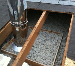
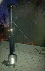
So, I bought my class A pipe and accessories over the weekend and planned to install it today. I got a good start but need to finish on another day. I have my heat shield and hearth project going at the same time. I just figured since a few nice days left, I better get the chimney installed before the weather gets too difficult to deal with.

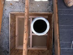
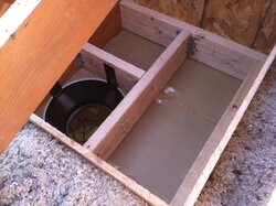
Today, I set the wood stove in the exact location relative to the combustible wall since clearances are measured from the nearest combustible surface. I left enough gap to accomodate the heat shield and river rock that is also in the construction phase, which was delayed due to special ordering some supplies.

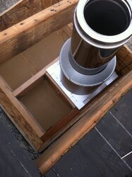
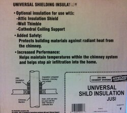
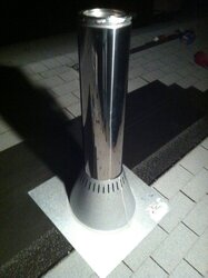
Selkirk's SuperVent class A chimney seems like a solid product. All the parts were in great shape right out of the box which is what I expected. The directions that came with the ceiling support contained errors, so I printed the updated directions from www.supervent.com. I recommend obtaining the directions from their website.

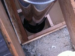
My home is a ranch with 4/12 pitch roof. The stove is located in my open concept living, dining, and kitchen. The chimney will go through my living room ceiling through the attic and out the roof. This is not a very tall installation. My overall height will be 14', which is the minimum recommended by Jotul.

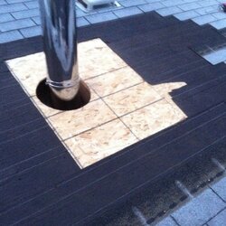
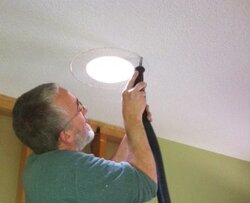
Step 1: Transfer the center of the stove exhaust to the ceiling.

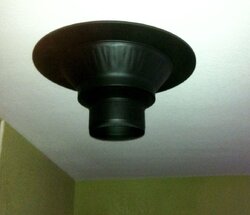
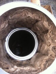
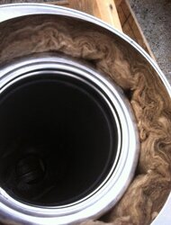
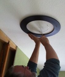
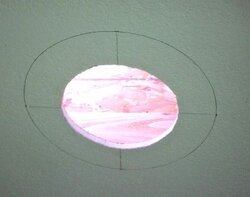
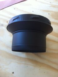
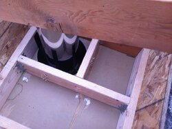
The wood stove exhaust is located on the top of the unit. I used a plumb bob to transfer the center of the exhaust flange on the stove to the ceiling. I did not include a photo of this step. The picture below shows the center point, two lines running through it creating an "x", and two concentric circles. The inner circle was created with a compass using the center point. I used my compass to create an 8" inner circle. My compass was too small to create a 12 3/8" circle, so I measured 6 3/16" from the center point along each leg of the "x" and made a mark. This gave me four points to center the ceiling support collar (large black ring in photo).

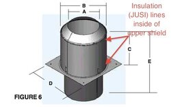
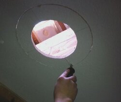
The inner circle is about 4" narrower than the actual finished opening of 12 3/8". I did this to double check my hole placement relative to the framing above in the event that I miscalculated. I knew I was close but 4" would allow for some final adjustment. By the way, the directions can seem confusing. Basically, if using the ceiling support, you'll need a 12 3/8" round hole in the drywall. You'll notice that I'm using the collar of the ceiling support as a template. The directions do not point out the benefit of doing this. It works great. Just be sure you use the inside of the collar, not the outside!!

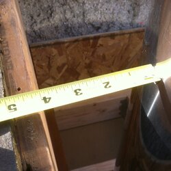
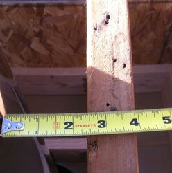
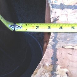
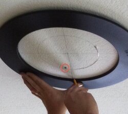
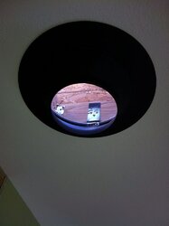
The second photo (close-up) shows more clearly the marks that I made. Notice the black dot within the red circle. That's actually a nail head. That was my first center mark. After cutting open my roof directly above the location for my chimney, I realized that I needed to move things a little bit. Sure glad I looked before cutting my ceiling out.
 

Attachments

  • SuperVent Chimney Stencil Ceiling.jpg
    SuperVent Chimney Stencil Ceiling.jpg
    19 KB · Views: 2,197
  • SuperVent Chimney Stencil Ceiling II.jpg
    SuperVent Chimney Stencil Ceiling II.jpg
    25.4 KB · Views: 2,190
Glad to hear your project is moving along. Keep us updated...more pics please.
 
Step 3: Check the outer circle for correct placement and then cut out.

Notice the vacuum hose in the first photo. I used a Ridgid shop vac with fine dust filter and fine dust collection bags. This minimizes dust in the house, keeping the kids and wife breathing easier.

The second photo shows more of close-up of my process. Notice the location of my keyhole saw. That was the first cut I made. I cut toward the edge of my outer 12 3/8" circle where my framing should meet with the edge of the circle. Luckily my measurements and planning were correct. My keyhole saw bumped into the wood framing just as the saw cut the drywall at the outer circle. Knowing that my layout was correct, I finished cutting out the outer circle.
 

Attachments

  • SuperVent Chimney Ceiling Cutout III.jpg
    SuperVent Chimney Ceiling Cutout III.jpg
    15.7 KB · Views: 1,720
  • SuperVent Chimney Ceiling Cutout II.jpg
    SuperVent Chimney Ceiling Cutout II.jpg
    12.1 KB · Views: 1,677
Step 4: Install framing above opening in ceiling and install decorator ceiling support.

The second photo shows the opening in the attic insulation that I framed out two years ago (when I air sealed and insulated my attic) in preparation for installing this chimney. Notice the OSB which holds back the rest of the attic insulation away from the chimney zone, as I call it. Should I ever need to open up my roof to work on my chimney, I'll be able to do so without disturbing the rest of the attic insulation. You can see a glimpse of the ceiling support in the lower left hand corner.

The first photo shows a detail view of the top side of the decorator ceiling support. Notice the red circles highlighting the 5 8d nails in each support strap. The manufacture suggests a minimum of 3 8d nails per support strap.

The third photo shows another view of the space.
 

Attachments

  • Attic View.jpg
    Attic View.jpg
    163.4 KB · Views: 2,880
  • SuperVent Chimney Decorator Ceiling Support Top View.jpg
    SuperVent Chimney Decorator Ceiling Support Top View.jpg
    79.8 KB · Views: 5,723
  • Attic View II.jpg
    Attic View II.jpg
    171.6 KB · Views: 2,914
The decorator ceiling support bottom view.
 

Attachments

  • Supervent Chimney Decorator Ceiling Support Bottom View.jpg
    Supervent Chimney Decorator Ceiling Support Bottom View.jpg
    52.9 KB · Views: 2,632
Step 5: Install stove pipe adaptor and first section of stove pipe.

The stove pipe adaptor has a lock and turn type connector on the top end, which gets inserted into the female end of the class A chimney section. The bottom end is crimped to accept stove pipe. I'll be using a single piece of double walled telescoping stove pipe to connect my stove to the chimney.

The second and third photos show the first section of pipe installed into the decorator ceiling support. The stove pipe adaptor is on the end of the class A chimney section that is pointing downward into the ceiling support. The stove pipe adaptor is not visible from this view.
 

Attachments

  • Stove Pipe Adaptor.jpg
    Stove Pipe Adaptor.jpg
    55.4 KB · Views: 3,447
  • First Section Class A Pipe.jpg
    First Section Class A Pipe.jpg
    171 KB · Views: 2,349
  • First Section Class A Pipe II.jpg
    First Section Class A Pipe II.jpg
    160.9 KB · Views: 2,356
Excellent forethought, planning, progress and photos!!! Please keep us updated as things proceed.
 
Blue2ndaries said:
Excellent forethought, planning, progress and photos!!! Please keep us updated as things proceed.

Thanks. I've been planning my stove and pipe installation for a while. I started collecting wood a year and a half ago. Now I've got almost all of next year's wood and starting on the year after that. You might say that I like to plan. LOL
 
Step 6: Test install of the attic insulation shield.

In the first photo you see the top view of the first section of class A chimney pipe. Notice the ceiling joist framing that surrounds the class A chimney pipe. This is where the attic insulation shield goes. Keep in mind that the ceiling joist framing is more than 2" from all sides of the class A chimney pipe. The angle of the picture is deceiving.

The second photo shows the attic insulation shield test fitted to be sure everything fits properly. Selkirk offers a universal insulation that fits inside the attic insulation shield wrapped around the class A chimney pipe. I'm using this insulation in my installation. The insulation is designed to prevent warm air from my home from entering the cool attic, which could cause condensation.
 

Attachments

  • First Section Class A Top View.jpg
    First Section Class A Top View.jpg
    166.6 KB · Views: 2,477
  • Test Fit Attic Insulation Shield.jpg
    Test Fit Attic Insulation Shield.jpg
    123.6 KB · Views: 4,355
Very nice documentation WoodNStuff. Thanks for the good pictures. Will you be backfilling insulation in the coffer dam after all is installed?
 
BeGreen said:
Very nice documentation WoodNStuff. Thanks for the good pictures. Will you be backfilling insulation in the coffer dam after all is installed?

BeGreen, I tip my hat to your fine compliments. You're a little ahead of me here. While my installation is already done, I'll let you see the next few posts to find out. Cheers!
 
Looking good......you're doing it the right way, and your documentation and photos will be a valuable asset to others down the road here on the Hearth .....keeping the pics coming!!
 
Scotty Overkill said:
Looking good......you're doing it the right way, and your documentation and photos will be a valuable asset to others down the road here on the Hearth .....keeping the pics coming!!

Scotty Overkill, tip of my hat to you sir on your fine looking stone chase. I might be asking you a few questions one of these days. Thanks for the good words. I'm trying to document as much as is useful. In the heat of the moment with impending rain, I now realize a couple photo ops missed. I've got more to post later.
 
Step 7: Install universal shielding insulation (JUSI).

The Selkirk Universal Shielding Insulation (part number JUSI) is designed to be placed between the exterior of the class A chimney pipe and the interior of the attic insulation shield. This insulation can also be used in Selkirk's cathedral ceiling support or their wall thimble.

See the box for the JUSI. It lists some of the benefits of the insulation as well as its applications. Notice the small diagram showing the location of the insulation in the attic ceiling support.

See the diagram (FIGURE 6) showing the attic insulation shield. The insulation is placed on the inside of the upper bell, such that the first section of class A chimney pipe can run through it.

Notice the picture of the insulation. Someone from the forums indicated that this is rock wool.

The last picture shows the JUSI installed inside the attic insulation shield. I set the attic insulation shield in a box to support it while adding the insulation.
 

Attachments

  • Attic Insulation Shield Diagram.jpg
    Attic Insulation Shield Diagram.jpg
    14.5 KB · Views: 3,425
  • Universal Shield Insulation Box.jpg
    Universal Shield Insulation Box.jpg
    171.7 KB · Views: 2,113
  • Universal Shield Insulation.jpg
    Universal Shield Insulation.jpg
    145.7 KB · Views: 1,968
  • Attic Insulation Shield With Insulation.jpg
    Attic Insulation Shield With Insulation.jpg
    95.8 KB · Views: 2,061
Step 8: Double check clearances to combustibles.

Check the clearances to the left side of the first section of class A chimney pipe. According Selkirk, 2" is the minimum clearance to combustibles. I have 4" on the left side.

Next check the clearances on the right side. I have 2 1/2". The picture was taken off angle so only shows 2 3/8". Either way, I'm good.
 

Attachments

  • Check Left Side of Chimney.jpg
    Check Left Side of Chimney.jpg
    102.4 KB · Views: 1,546
  • Check Right Side of Chimney.jpg
    Check Right Side of Chimney.jpg
    106.4 KB · Views: 1,487
Step 9: Install attic insulation shield.

The first photo shows the first section of class A chimney as the attic insulation shield is being slid over it.

The second photo shows the first section of class A chimney as the attic insulation shield is almost fully slid over it.

The third photo shows the attic insulation shield slid all the way down the class A chimney section and fully seated on the ceiling joists. Notice the screws. Selkirk's instructions indicated at least two 1" #8 wood screws are required on each of the four sides. I installed enough screws evenly spaced around the perimeter to keep the edge fully seated. This I believe is important, thus preventing insulation from getting under the shield.
 

Attachments

  • Attic Insulation Shield Installation I.jpg
    Attic Insulation Shield Installation I.jpg
    128.7 KB · Views: 2,091
  • Attic Insulation Shield Installation II.jpg
    Attic Insulation Shield Installation II.jpg
    115.7 KB · Views: 1,893
  • Attic Insulation Shield Screwed.jpg
    Attic Insulation Shield Screwed.jpg
    175.3 KB · Views: 6,270
WoodNStuff said:
Scotty Overkill said:
Looking good......you're doing it the right way, and your documentation and photos will be a valuable asset to others down the road here on the Hearth .....keeping the pics coming!!

Scotty Overkill, tip of my hat to you sir on your fine looking stone chase. I might be asking you a few questions one of these days. Thanks for the good words. I'm trying to document as much as is useful. In the heat of the moment with impending rain, I now realize a couple photo ops missed. I've got more to post later.
thank you for your compliments, any time you need anything feel free to PM me.....I will post some pics soon too, as I get a little more done....been a bit hectic on my project but I did get the stone sealed and got the chase insulated, just have a couple of other things to do before I install the fireplace.....keep use posted on your project looks great so far....
 
Step 10: Re-insulate and install sheathing.

Initially, I removed the insulation that was in the area where the chimney was to be installed. Now, I just poured it back in place around the insulation shield.

The second photo shows the new roof sheathing fit in around the chimney. Notice the clearance around the class A chimney pipe.
 

Attachments

  • Reinstall Insulation.jpg
    Reinstall Insulation.jpg
    188.6 KB · Views: 1,968
  • Sheething Installed.jpg
    Sheething Installed.jpg
    201.9 KB · Views: 1,921
Step 11: Double check roof sheathing clearances.

It's 3" all the way around, except on the right hand side (pictured) where the rafter is 2 1/2". The minimum clearance is 2" to combustibles. So with 2 1/2" to 3" I'm extra good.
 

Attachments

  • Sheathing Clearance.jpg
    Sheathing Clearance.jpg
    103.2 KB · Views: 1,289
keninmich said:
Great pics....great work on your part.

Thanks for posting it all....

Thanks keninmich. It was a lot of fun. Now I want to install another one. My buddy might put in a wood stove. So, perhaps I'll help him with his chimney install.
 
Status
Not open for further replies.