St Croix auger feeds continuously, big pile of pellets!

  • Active since 1995, Hearth.com is THE place on the internet for free information and advice about wood stoves, pellet stoves and other energy saving equipment.

    We strive to provide opinions, articles, discussions and history related to Hearth Products and in a more general sense, energy issues.

    We promote the EFFICIENT, RESPONSIBLE, CLEAN and SAFE use of all fuels, whether renewable or fossil.
Status
Not open for further replies.

8_Star

New Member
Feb 7, 2014
11
BC, Canada
Hello, I'm running a St. Croix Pepin stove. When I turned on the power this morning, I saw a bright flash and the glass fuse blew inside (it does this maybe once a year, so it didn't seem unusual to me). I replaced, turned it back on, and now the auger motor will not stop turning. The feed light from the control panel comes on and off at the proper intervals but the auger turns regardless, and won't stop feeding pellets, no matter what I change the settings to.

Wires and connections all look good and snug.

Any ideas would be greatly appreciated, it is -16 today up North! Yikes
Thanks a ton
 
Last edited:
Sounds like a relay fused shut and is now feeding without letup:( I know the pain of cold, -14 F this AM now up to a whopping -22C but the sun is out.
 
Might use triac instead of a relay to apply 110VAC to the auger motor. Replace the triac, about $3 for the part.
 
Might use triac instead of a relay to apply 110VAC to the auger motor. Replace the triac, about $3 for the part.

TRIAC, from Triode for Alternating Current, is a genericized tradename for an electronic component that can conduct current in either direction when it is triggered (turned on), and is formally called a bidirectional triode thyristor or bilateral triode thyristor.

I didn't know so I thought I would share my new found knowledge.
Thanks
 
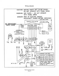
OK, the auger motor has two red wires attached to it, the first is connected to a terminal block and is joined with ORANGE and YELLOW. I disconnected the ORANGE and tested the voltage with a multimeter and it gives constant 120v. I disconnected YELLOW and tested the voltage and got a constant 8V.

Both yellow and orange are directly connected to the control panel's wiring harness.

I would think that the control box should be sending some on/off voltage to control the start and stop the auger, and I'm not sure which wire this would be. I thought it would be ORANGE, but it reads a constant 120V.

Pepin wiring.jpg
 
Last edited by a moderator:
OK, in the service manual it says the orange wire is the "manual feed", so it seems like it is stuck in constant manual feed.
 
The auger motor circuit works like this :
1) 110VAC hot goes thru the fuse to the circuit board molex connector pin # 3
2) The auger motor TRIAC (or relay) completes the circuit from board connector pin #3 to board connector pin #5, when the auger motor is supposed to run.
3) Board connector pin #5 then supplies current to the auger motor, connected to TB1
4) The other auger motor wire then connects to TB3, completing th circuit to the other prong of the 110VAC wall plug.
The TRIAC or relay is stuck/shorted ON, all the time. With the wall plug disconnected, use a meter to measure (Ohm scale) from board connector pin # 5 to board connector pin # 3. I bet it is under 10 ohms (shorted triac or relay.
Post a close-up picture of the control board so I can see if it uses a triac or a relay.
 
  • Like
Reactions: 8_Star
Thanks, great info!
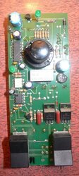
Here's the control board
-With everything off and unplugged I get no continuity whatsoever from #3 to #5 at the board's molex connector
-I get 6 Ohms between #3 and #4

P1120179.jpg
 
OK, correction, I took a closer look at the schematic, : the triac or relay is between board terminals #3 and #4. The auger motor current flows thru three safety switches, which open if there is a stove overtemp condition. From your meter readings, you found the short.

From your picture of the back of the board, I can't see a triac device, but it is probably mounted to the front of the board. There is a relay (black rectangular box) on the back of the board, but I suspect that is for the ignitor. To verify the relay is for the ignitor, trace the ignitor wire terminals, and see if the green copper board traces connect to any of the relay terminals. It looks like the right side ignitor wire goes straight up to the relay.

If you can follow the green board trace from the #4 connector pin, it should lead to the triac device.

Can you take a picture of the front side of the board?
 
Last edited:
To verify the relay is for the ignitor, trace the ignitor wire terminals, and see if the green copper board traces connect to any of the relay terminals. It looks like the right side ignitor wire goes straight up to the relay.

If you can follow the green board trace from the #4 connector pin, it should lead to the triac device.

Can you take a picture of the front side of the board?

I'm having trouble taking the board away from the control panel, the heat adjustment knob and power/manual feed switches are fastened in a way I can't make sense of :) Maybe there's a trick, I can't see it. I've loosened the nut on the shaft of the heat adjustment control but I need the knob to come off to separate the board from the metal panel.

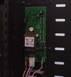
Still, peering through the side, I can't see any obvious lines tracing from pin #4... here are some more detailed photos, I added a red dot to pin #4 in each of the photos for reference. I also included a side view, maybe you can see the triac or another relay, I don't have very experienced eyes with circuit boards.

I checked again and I still get 6 Ohms from pin #4 to pin #3, so it must be shorted somewhere.
(And to answer an earlier question, yes, the ignition wire traces straight to that black relay.)


pin4backview.jpg

pin4frontview.jpg
controlbox sideview.jpg
 
Sounds like a relay fused shut and is now feeding without letup:( I know the pain of cold, -14 F this AM now up to a whopping -22C but the sun is out.
Hmm... Just give me the facts in degrees Fahrenheit all the way around... Lol! Dang Minnesotans ya know!
 
Hmm... Just give me the facts in degrees Fahrenheit all the way around... Lol! Dang Minnesotans ya know!
Was for the benefit of the Canadian OP. Can't have him think its nice and balmy down here in the land of ten thousand taxes:)
 
I'm having trouble taking the board away from the control panel, the heat adjustment knob and power/manual feed switches are fastened in a way I can't make sense of :) Maybe there's a trick, I can't see it. I've loosened the nut on the shaft of the heat adjustment control but I need the knob to come off to separate the board from the metal panel.
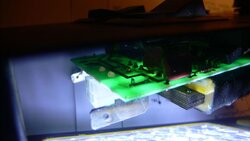
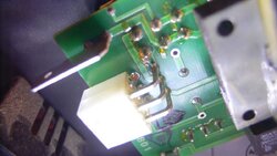
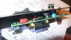
Still, peering through the side, I can't see any obvious lines tracing from pin #4... here are some more detailed photos, I added a red dot to pin #4 in each of the photos for reference. I also included a side view, maybe you can see the triac or another relay, I don't have very experienced eyes with circuit boards.

I checked again and I still get 6 Ohms from pin #4 to pin #3, so it must be shorted somewhere.
(And to answer an earlier question, yes, the ignition wire traces straight to that black relay.)


View attachment 126865

View attachment 126866
View attachment 126864
I'll try to help.First,see the set screw inside the knob?Bad news,this type of set up you have to unsolder the switches and possibly the leds to remove board,probably a little more than you want to get in to.Good news,the old styles are almost always repairable.St croix had board/harness for all their stoves except the pepin,may have been only because of mounting problems,something to check in the summer.Any older tv tech,or ham radio guy could help you out,start calling your friends.Most places can repair that board but may not be able to test the functions.Assembled products advertises they fix all.If desperate,look up jason munson's you tube video on temporary manual stove controller,could get you by,but you would only want to use it when you are home.Good luck,Bob
 
  • Like
Reactions: 8_Star
I'll try to help.First,see the set screw inside the knob?Bad news,this type of set up you have to unsolder the switches and possibly the leds to remove board,probably a little more than you want to get in to.Good news,the old styles are almost always repairable.

Ha! Got the set screw, totally missed that... thanks.... LEDs slide out cleanly.... and I just figured out the switches, they have a little black clip on the backside of the bevel, if you pull those tabs with long nose pliers the bevel can pop out the front, then the switches slide out cleanly.
 
Last edited:
Good job,now you need someone smarter than me.I can tell you with an old style like this,you have to have a timer and logic circuit.your problem is probably nothing you will see with the eye.Also,if your board has an auger position on one of the switches,to run auger to fill for statring,switch could be stuck.Now that you got it to where it can be tested would be time to have a electronics guy come over,Sorry I cannot help more.Bob
 
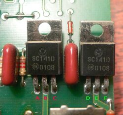
There are two triacs, the two three-terminal parts, black plastic body, with the metal tab with a hole in it : both are right above the right switch in the last picture, marked "SC141D". Use you meter to find continuity from board connector pin #4 to one of the three pins of one of the triacs. That is the triac that is bad.
 
There are two triacs, the two three-terminal parts, black plastic body, with the metal tab with a hole in it : both are right above the right switch in the last picture, marked "SC141D". Use you meter to find continuity from board connector pin #4 to one of the three pins of one of the triacs. That is the triac that is bad.
Good catch NJ,I did not bother checking numbers because I have never seen triacs not bolted to a heat sink,learn something new everyday!
 
This is great progress :)

Thanks everyone

So I added some letters below each of the connections on the two triacs (in the photo below), and here's what I found for continuity:

Between pin #4 and.....
A = full continuity (0.06)
B = full continuity (0.06)
C = some resistance (0.55)

D = full continuity (0.06)
E = has NO continuity (1)
F = some resistance (0.55)


So..... is triac 'ABC' the culprit?


triac-closeup.jpg
 
Does terminal/trace 4 go to it?Anyway,just the fact you see a difference says something,replace both,they are about $3 each.
 
Looks like the left triac "ABC is the bad one.
Verify by using the resistance scale of your meter, and probing the two pins of each triac, A B, (or D E). Probably the 6 ohms you measured earlier will be present on A B.
 
  • Like
Reactions: Xena
they cost a bit more than I am used to.
and as an added bonus.... $13 shipping to Canada... never knew triacs were so heavy?? :p
might have to quickly shop around a bit

Looks like the left triac "ABC is the bad one.
Verify by using the resistance scale of your meter, and probing the two pins of each triac, A B, (or D E). Probably the 6 ohms you measured earlier will be present on A B.

Yes, 6 Ohms present on A B
No continuity on D E

Ok, I'll order me a brand new triac and see what happens!
I'll post the results when I get it installed. THANK YOU ALL!
 
Status
Not open for further replies.