
No, took temps where pex goes into slab in barn and where it comes through foundation in boiler room.I assume supply at the tank is 179 and it is 176 by the time it gets to the close tee?
Most pre-insulated CLAIMS 1F/100' at 5gpm.
ac
Storage and programable thermostats
- Thread starter Coal Reaper
- Start date
-
Active since 1995, Hearth.com is THE place on the internet for free information and advice about wood stoves, pellet stoves and other energy saving equipment.
We strive to provide opinions, articles, discussions and history related to Hearth Products and in a more general sense, energy issues.
We promote the EFFICIENT, RESPONSIBLE, CLEAN and SAFE use of all fuels, whether renewable or fossil.
You are using an out of date browser. It may not display this or other websites correctly.
You should upgrade or use an alternative browser.
You should upgrade or use an alternative browser.
- Status
- Not open for further replies.
avc8130
Minister of Fire
No, took temps where pex goes into slab in barn and where it comes through foundation in boiler room.
So ~2F/100'. No clue how that compares REALLY to pre-insulated pipe. Some wrapped pipe claims ~.5F/100'. Thermopex claims <1F/100'.
As we all know there are many variables.
The wrapped pipe claims are at 180F supply and 5gpm.
Thermopex? Unknown.
What condition did you measure?
ac
avc8130
Minister of Fire
Speed 1
How many gpm?
According to Taco's pump curve for speed 1, you should be "dead headed" and have no flow.
ac
Go figureHow many gpm?
According to Taco's pump curve for speed 1, you should be "dead headed" and have no flow.
ac
avc8130
Minister of Fire
As i have said it aint much flow
Any chance is it convective? Or maybe your 007 zone pump adding to it?
Crazy idea, but what happens if you turn off the BB?
avc8130
Minister of Fire
Does the flow stop? clearly something is off. Maybe your head calculation?
Taco themselves say the pumps always follow the curve.
Speed 1 for you is 0 flow. Maybe it IS working as designed. Does it ever kick up to speed 2?
Taco themselves say the pumps always follow the curve.
Speed 1 for you is 0 flow. Maybe it IS working as designed. Does it ever kick up to speed 2?
ewdudley
Minister of Fire
In a circulation circuit where static head is zero, the intersection of the pump curve and the system curve is necessarily at some non-zero flow rate.Does the flow stop? clearly something is off. Maybe your head calculation?
Taco themselves say the pumps always follow the curve.
Speed 1 for you is 0 flow. Maybe it IS working as designed. Does it ever kick up to speed 2?
IDK if you can play around with the numbers quite the way i am but...Does the flow stop? clearly something is off. Maybe your head calculation?
Taco themselves say the pumps always follow the curve.
Speed 1 for you is 0 flow. Maybe it IS working as designed. Does it ever kick up to speed 2?
if i "ask" for 100kbtus/hr at 80* deltaT, that drops my flow rate to 2.78gpm and head to 2.2' even using 500' equivelent length which is within the speed1 curve. head is a function of flow rate, among other things. perhaps that is why i am seeing accoasional 12-16 watts instead of just 9? everything might be working just fine...
supply temp was down to 140* this morning (100* at bottom of tanks) so i will recharge tanks tonight. the last fire was saturday morning. tstat is at 65*, gets to 68 during the day with solar gain. have only been heating at night with temps dipping down into low 50s, but wife is warm and i am happy.
avc8130
Minister of Fire

In a circulation circuit where static head is zero, the intersection of the pump curve and the system curve is necessarily at some non-zero flow rate.
Care to translate that with reference to the BB pump curve?
avc8130
Minister of Fire
IDK if you can play around with the numbers quite the way i am but...
if i "ask" for 100kbtus/hr at 80* deltaT, that drops my flow rate to 2.78gpm and head to 2.2' even using 500' equivelent length which is within the speed1 curve. head is a function of flow rate, among other things. perhaps that is why i am seeing accoasional 12-16 watts instead of just 9? everything might be working just fine...
supply temp was down to 140* this morning (100* at bottom of tanks) so i will recharge tanks tonight. the last fire was saturday morning. tstat is at 65*, gets to 68 during the day with solar gain. have only been heating at night with temps dipping down into low 50s, but wife is warm and i am happy.
The math must work.
65? What is this? You ain't heating with oil any more!
ac

ewdudley
Minister of Fire
To estimate circuit flow you need a pump curve and a system curve. The 'system curve' is a plot of head loss as a function of gpm for the particular circuit in question. All you need to do is plot the system curve on top of the pump curve and where they intersect will give you the flow rate for the pump and circuit in question. My WAG for this situation would be somewhere between 2 and 4 gpm for the lowest pump curve.
Unless system curve has a vertical segment on the ordinate axis (static head) then there will be some non-zero flow rate where the curves intersect. Closed circulation loops have no static head except perhaps a little from an IFC or some such.
Last edited:
preggo said 68 was too much!The math must work.
65? What is this? You ain't heating with oil any more!
ac
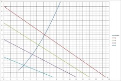
like this?To estimate circuit flow you need a pump curve and a system curve. The 'system curve' is a plot of head loss as a function of gpm for the particular circuit in question. All you need to do is plot the system curve on top of the pump curve and where they intersect will give you the flow rate for the pump and circuit in question. My WAG for this situation would be somewhere between 2 and 4 gpm for the lowest pump curve.
Unless system curve has a vertical segment on the ordinate axis (static head) then there will be some non-zero flow rate where the curves intersect. Closed circulation loops have no static head except perhaps a little from an IFC or some such.
Attachments
ewdudley
Minister of Fire
You got it. If you google:like this?
"system curve" "pump curve" circulator
you'll see lots of them just like yours.
awesome, thanks for your help. FWIW,my graph says i am pumping half the water of what the hec2 display shows. its nice to know how responsive my system is at 6gpm on speed4 AND that at speed1 is only moving 3gpm.You got it. If you google:
"system curve" "pump curve" circulator
you'll see lots of them just like yours.
Some more accurate numbers for you:So ~2F/100'. No clue how that compares REALLY to pre-insulated pipe. Some wrapped pipe claims ~.5F/100'. Thermopex claims <1F/100'.
As we all know there are many variables.
The wrapped pipe claims are at 180F supply and 5gpm.
Thermopex? Unknown.
What condition did you measure?
ac
At 6gpm through 165' i see 154.6*f drop to 153.5*
I will record again with higher temps after i have a fire.
avc8130
Minister of Fire
Some more accurate numbers for you:
At 6gpm through 165' i see 154.6*f drop to 153.5*
I will record again with higher temps after i have a fire.
Can't complain about that!
ac
- Status
- Not open for further replies.
Similar threads
- Replies
- 9
- Views
- 2K
- Replies
- 10
- Views
- 2K
- Replies
- 4
- Views
- 1K
- Replies
- 4
- Views
- 787