Storage - Plate HX - Layout

  • Active since 1995, Hearth.com is THE place on the internet for free information and advice about wood stoves, pellet stoves and other energy saving equipment.

    We strive to provide opinions, articles, discussions and history related to Hearth Products and in a more general sense, energy issues.

    We promote the EFFICIENT, RESPONSIBLE, CLEAN and SAFE use of all fuels, whether renewable or fossil.
Status
Not open for further replies.

WoodNotOil

Minister of Fire
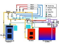
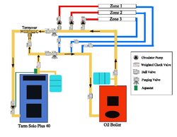
Here is my current thinking on how I can layout the piping for the open storage tank I am making. The first image is my current piping and the second is the planned piping.

Heating of tank - Pumps 1 & 4 come on together. Heated water travels through the oil boiler incase zones call for heat and then through the HX

Drawing from tank - Pumps 2 & 3 come on together. This circulates water from the oil boiler through the exchange. My DHW is always drawn from a coil in the oil boiler and all of the zones are fed from oil boiler.

A SPDT relay would be used to make sure all pumps do not run simultaneously (idea from nofossil)

I understand that my parallel piping is a variation from most, so I have tried to work things out as best I can based on what I currently have. There are two pumps on the tank side of the HX to maintain stratification.

The tank will be 930 gallons made of concrete in the basement corner with an EPDM liner and well insulated with polyiso.

Any feedback would be greatly appreciated.
 

Attachments

  • Parallel Piping -Plate HX Storage.JPG
    Parallel Piping -Plate HX Storage.JPG
    77.6 KB · Views: 550
  • Parallel Piping Layout.JPG
    Parallel Piping Layout.JPG
    62.5 KB · Views: 516
Looks like you're running the output of the Tarm through the oil boiler and vide versa. Also looks like there's always flow through the boiler side of the flat plate.

My suggestion would be along these lines:

1) The wood boiler, oil boiler, and the boiler half of the HX all have their own circulators with check valves.

2) All three are plumbed in parallel, each drawing from the same return manifold and each pumping to the same supply manifold.

3) There is a zone valve in parallel with the HX circulator that can be opened when you want to charge the tank from one of the other heat sources.

4) Aquastats on the Tarm and storage are used to determine whether heat comes from the Tarm, Storage, or Oil (Tarm is hot: source=Tarm, Tarm is not hot and storage is hot: source=storage. Neither is hot: source=oil). Only the selected source can have its circulator active.

5) If the Tarm is hot and there's no thermostat demand, open the zone valve to allow flow through the HX. Also turn on the tank side HX circ that draws from the bottom.

6) If Storage is the selected heat source and there's thermostat demand, turn on the boiler side hx circ and the tank side hx circ that draws from the top.

Does this approach make sense? I don't have time to do a drawing right now.
 
Alright, I give up. Here's a drawing of what I was thinking. Any resemblance to my own configuration is intentional. I don't think you can get much simpler and still have the functionality that you're looking for.

In this setup, no more than two pumps will ever run at one time. You will need a bit of creativity with relays or with a simple controller to get everything playing nice, but there are only a few well-defined modes of operation:

1) Oil heating house zones
2) Tarm heating house zones
3) Tarm heating storage
4) Storage heating house zones

Perhaps modes 2 and 3 could happen at the same time under some conditions, but that's about as complex as it gets.
 

Attachments

  • woodnotoil.gif
    woodnotoil.gif
    36.4 KB · Views: 545
nofossil - thanks for the feedback. If I was starting from scratch, that is probably the way I would do it. However, I do not want to have to repipe the existing system (too expensive and time consuming). In my design I ran the output of the tarm through oil boiler while charging the tank to ensure there would be hot water for the zones during charge. The purpose of my tank is to keep the oil boiler hot when the tarm is not charging. My design would also allow the tank to be charged using the oil boiler (not that I will probably ever do that). I know it is not the typical setup, but I think it would work and give me the same options your design does. (Except running house zones off of tarm directly). Do you think it would work as I intend it to?
 
I don't quite see the intended flow paths.

The oil boiler has its own circ that's not shown?

Looks like the oil would always be dumping some heat into storage unless you manually close an isolation valve.

When would the circ in the red line be energized? Strike that - read your description again. The path for withdrawing heat from the tank seems strange - let me ponder.
 
Nofossil - It flows out of the top of the oil boiler, along the purple line, through the HX, through the red line where the pump is, and then back into the oil boiler. Strange I know, but I think it would work.
 
WoodNotOil said:
Nofossil - It flows out of the top of the oil boiler, along the purple line, through the HX, through the red line where the pump is, and then back into the oil boiler. Strange I know, but I think it would work.

If the oil boiler circ (assumed to exist, but not shown) is equal to or less than than the 007, then there will be no flow to the zones. I think.
 
The oil boiler circ is pump 3 on the red line (it exists and is shown). The zones each have their own pump, not zone valves. So if the zones are running the oil boiler circ will compete with those. Each zone has an 007 or equivilent. Not sure if that will be a problem or not. If all three zones and the oil boiler circ happened to be running, I would guess each would be getting 1/4 of the flow. However, in actuallity it may not be that simple.
 
OK, so no oil circ in the first diagram - just used the zone circs I assume.,

As I read it then, when heating with the Tarm, the hot outlet from the tarm is mixed with the cold return from the zones, then fed through the oil boiler, then to the zones and back to the Tarm.

When heating with oil, pump number 3 is not used unless you want to heat the tank?

When heating from the tank, the hot tank output is mixed with the cold zone returns. passed through the oil boiler, and then fed to the zones?

I'll let someone else jump in with ideas, but if it were me, I'd get out the torch at this point and do either true parallel or a primary / secondary loop system.
 
Nofossil - Thanks again for all the feedback, you have some good ideas. I am still trying to understand the different ways to pipe boilers in parallel. My contractor and I used this piping concept from Tarm
http://www.woodboilers.com/_img/pl_parallel.gif
to set them up in parallel. Your piping design looks more like their primary/secondary http://www.woodboilers.com/_img/pl_primarysecondary.gif

My hope is that there is a way to work off of the original concept and not have to repipe. Hopefully someone else will chime in with some suggestions as well.
 
Status
Not open for further replies.