Systemic dreaming...

  • Active since 1995, Hearth.com is THE place on the internet for free information and advice about wood stoves, pellet stoves and other energy saving equipment.

    We strive to provide opinions, articles, discussions and history related to Hearth Products and in a more general sense, energy issues.

    We promote the EFFICIENT, RESPONSIBLE, CLEAN and SAFE use of all fuels, whether renewable or fossil.
Status
Not open for further replies.
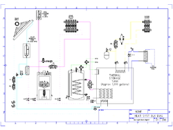
Bringing this thread back up as I've finally gotten my initial layout diagram done... Figured I'd post it and see what people thought. The attached is a .png file that I hope is legible - it looks nice as a .dxf, but I can't post those... (If you want that version, send me a PM w/ an e-mail address...)

I know it is complex, but let me see if I can explain it - if any one sees any glitches, please let me know.

SOLAR LOOP:

Our house has several attic spaces due to it's design, and one is in the lower half of the roof, which allows the use of a closed "drainback" type system with the tank mounted just below the collectors, minimizing the "lift height" required to fill them. It will slightly reduce the maximum size of the array that I could use, but it will allow me to avoid using glycol in that loop, and reduces the potential problems caused by stagnation, as the collectors would be filled with air in such a condition, rather than water. It is something I've seen in both Siegenthaler articles and on the Caleffi website.

P1 and P2 are in series, both operate at startup, but once the system is flowing, one can carry the load so the other is shut down - It may be worth making one of them speed controled to better match the panel output. The water to fill the array comes from the drainback tank, and the air in the array is displaced into the tank. Note that this system is sealed and pressurized to avoid O2 issues. When the circs shut off, the solar collectors drain back to the tank, and the air goes up to the array. The drainback tank also does duty as an expansion tank and air separator.

If the house is calling for heat, and the array is hotter than the house loops require, Z-A switches to force flow through the plate exchanger, which feeds the house loops via P3, Z-F and Z-H, otherwise it bypasses.
If the house loops don't need the heat, and / or if the return is warmer than the bottom of the thermal storage tank, Z-B sends water through the storage tank coil, otherwise it bypasses.
(I may add a third loop to the hot water storage tank, using a similar logic - not sure if it would be justifiable)
If neither load is cooler than the solar array, shut it down or modulate the circ for a lower flow rate / higher temp.

The idea is to send the solar output to the lowest temperature demand that can use it, as the lower the operating temperature, the more efficient the array is.

By having heat exchangers going to both the house loop directly and the storage tank, I can still use the solar array for house heating, even if the storage tank is hotter than the array. My theory is that I would mostly be building fires in the late afternoon or at night, when the array is shut down, and doing house heating and storage charging. In the day, the boiler would be burned out and cold, so by heating off the array and leaving the charged storage alone, I should get more time out of the storage before needing to build the next fire.

BOILER LOOP:

The boiler loop is pressurized by an OPEN expansion tank in our highest attic space - between 20 and 30 feet above the boiler room. This should give a 10-15psi working pressure at the boiler, but as the system is "open" avoid the stupid MA requirement for an ASME "H" stamp boiler. :coolsmirk: (This per Chris @ BioHeat)

If heat is being supplied by the boiler, or the solar heat exchanger, P3 runs, sending the heat to the house loops (controlled by Z-H), the DHW indirect (controlled by Z-J) or the main storage tank coil (controlled by Z-K). If running off the storage tank, P4 runs reversing the direction of flow in the main branch. P3 and P4 should probably be speed controlled. If P3 especially is speed controlled low enough, then it avoids the need for a Termovar or other boiler return protection - the pump won't pull more heat out of the boiler than it's making...

Note that right now I am showing the house loops as a single set of radiant loops controlled by Z-H - this is mostly because I haven't really tried to get the house side down on paper yet... In practice, I'm sure there will be many house circuits, each with their own zone-valve - however I don't think this will change the basic concept any.

DHW LOOP:

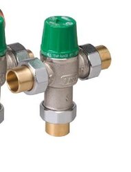
I'm swiping NoFossil's idea here of using dual mixing valves in order to get the most out of our hot water - when there is a hot water call, the makeup water to the indirect tank and the mix water to the first mix valve is pre-heated by a small coil in the storage tank, thus reducing the amount of peak temperature water pulled from the indirect tank. The second mix valve adds in cold DHW to give the final 120* output. (In theory if the storage tank were hot enough, there would be NO draw on the indirect...

GARAGE LOOP:

Simple standard style glycol loop to feed an occasional demand to warm up the garage - If I have to work out there I don't want to freeze my a(natomy) off... The heater will probably be a "Modine" style, but again the concept doesn't change...

POOL LOOP:

The place I have in mind for the storage tank is very close to our pool - it seems ideal for a gravity loop from the storage tank to the center of a sidearm type exchanger, with the outside tied into the swimming pool filter circuit... Z-X would control this loop during swimming season, when the pool is closed, simply opening the valve at the top of the loop will let it drain and shut off the flow.

So how does it look?

Gooserider
 

Attachments

  • heat_syst_block_diag-1a.png
    heat_syst_block_diag-1a.png
    13 KB · Views: 428
nofossil said:
I think it all makes sense. P4 has no check valve and you flow backwards through it when charging storage?

Exactly... P3 doesn't have one currently, but it could, and that might even be an improvement... No need for heat to get into that area when running off the storage.

Right now as it's drawn, I don't have any check valves anywhere in the system. I've just been reading a bunch of Siggy articles from PM magazine (great resource BTW) and have realized I need to go back and stick them in.

Gooserider
 
Gooserider said:
nofossil said:
I think it all makes sense. P4 has no check valve and you flow backwards through it when charging storage?

Exactly... P3 doesn't have one currently, but it could, and that might even be an improvement... No need for heat to get into that area when running off the storage.

Right now as it's drawn, I don't have any check valves anywhere in the system. I've just been reading a bunch of Siggy articles from PM magazine (great resource BTW) and have realized I need to go back and stick them in.

Gooserider

From my experience, the built-in check valves in circulators are better than external check valves. All the external ones that I've found have too much back pressure OR leak backwards OR both.
 
nofossil said:
Gooserider said:
nofossil said:
I think it all makes sense. P4 has no check valve and you flow backwards through it when charging storage?

Exactly... P3 doesn't have one currently, but it could, and that might even be an improvement... No need for heat to get into that area when running off the storage.

Right now as it's drawn, I don't have any check valves anywhere in the system. I've just been reading a bunch of Siggy articles from PM magazine (great resource BTW) and have realized I need to go back and stick them in.

Gooserider

From my experience, the built-in check valves in circulators are better than external check valves. All the external ones that I've found have too much back pressure OR leak backwards OR both.

That matches with what I've heard in terms of the flow resistance - which seems mildly odd given that we are also told to keep other sources of turbulence (like the external checks) a few diameters away from the circ inlets and outlets...

I hadn't heard about the leaking backwards issue, though it doesn't totally surprise me, as it seems like there is always a conflict between easy operation and leak resistance... However do they resist the backwards leaking at least enough to stop the ghost flow - that's all they are supposed to do after all...

Gooserider
 
Gooserider said:
nofossil said:
Gooserider said:
nofossil said:
I think it all makes sense. P4 has no check valve and you flow backwards through it when charging storage?

Exactly... P3 doesn't have one currently, but it could, and that might even be an improvement... No need for heat to get into that area when running off the storage.

Right now as it's drawn, I don't have any check valves anywhere in the system. I've just been reading a bunch of Siggy articles from PM magazine (great resource BTW) and have realized I need to go back and stick them in.

Gooserider

From my experience, the built-in check valves in circulators are better than external check valves. All the external ones that I've found have too much back pressure OR leak backwards OR both.

That matches with what I've heard in terms of the flow resistance - which seems mildly odd given that we are also told to keep other sources of turbulence (like the external checks) a few diameters away from the circ inlets and outlets...


Gooserider

Last year when I called and spoke with a tech at Wilo North America to try to find out whether they yet had any moderate cost residential-scale ECM circulators (which they didn't quite yet have to market then) I happened to ask about the check valve in pump issue and the paradox that you mention above. According to him (and he seemed informed, practical, and thorough) putting a check valve within the pump body is not the best idea from the standpoint of how it interacts with/ affects flow and efficiency in and by the pump-- he said that it's done more in response to installers' or designers' desire to kill two birds with one stone.
 
A couple thoughts.. Check that basement load again, sounds awful high even if some is above ground. same for the load on that great room 60 BTU/ sq foot sounds more like a snowmelt load number :)

It may be worth getting an architect involved, even for an hour consultation. They see and know things that could save you money, hassle, and provide a better end product. Same with a GC just to get code compliant input.

I agree focus on the building envelop, additions, etc first, then redo the load calc, room by room is best.

Checkout Siggy Heat Load Pro software, it has a basement calculator which helps a lot, may be a trial version at www.hydronicpros.com.

hr
 
pybyr said:
Gooserider said:
nofossil said:
Gooserider said:
nofossil said:
I think it all makes sense. P4 has no check valve and you flow backwards through it when charging storage?

Exactly... P3 doesn't have one currently, but it could, and that might even be an improvement... No need for heat to get into that area when running off the storage.

Right now as it's drawn, I don't have any check valves anywhere in the system. I've just been reading a bunch of Siggy articles from PM magazine (great resource BTW) and have realized I need to go back and stick them in.

Gooserider

From my experience, the built-in check valves in circulators are better than external check valves. All the external ones that I've found have too much back pressure OR leak backwards OR both.

That matches with what I've heard in terms of the flow resistance - which seems mildly odd given that we are also told to keep other sources of turbulence (like the external checks) a few diameters away from the circ inlets and outlets...


Gooserider

Gooserider

Last year when I called and spoke with a tech at Wilo North America to try to find out whether they yet had any moderate cost residential-scale ECM circulators (which they didn't quite yet have to market then) I happened to ask about the check valve in pump issue and the paradox that you mention above. According to him (and he seemed informed, practical, and thorough) putting a check valve within the pump body is not the best idea from the standpoint of how it interacts with/ affects flow and efficiency in and by the pump-- he said that it's done more in response to installers' or designers' desire to kill two birds with one stone.

Interesting, and I can sort of believe it - except that the curves I've seen from Taco and Caleffi seem to show that while there IS an impact on the pump curve, the circ plus internal check has less of a problem than the total of a circ plus an external flow-check. I think I've seen the same thing from some of Siggy's articles...
 
in hot water said:
A couple thoughts.. Check that basement load again, sounds awful high even if some is above ground. same for the load on that great room 60 BTU/ sq foot sounds more like a snowmelt load number :)

It may be worth getting an architect involved, even for an hour consultation. They see and know things that could save you money, hassle, and provide a better end product. Same with a GC just to get code compliant input.

I agree focus on the building envelop, additions, etc first, then redo the load calc, room by room is best.

Checkout Siggy Heat Load Pro software, it has a basement calculator which helps a lot, may be a trial version at www.hydronicpros.com.

hr

I got the numbers I mentioned from the Slantfin calculator, but I did have to fudge around with it a bit as it doesn't have choices that fit a lot of our house - especially for the living room and basement - However I suspect that both numbers aren't that far off - the basement is poorly insulated and the living room has a LOT of exposed walls - essentially it is the 1/3 of the house with those big windows - 23.5 feet from floor to the center of the ceiling - when the ceiling fan died, I had to rent and build a scaffolding tower in the middle of the room to get up to change it...

I will try to figure out a way to post my worksheets from the Slant-fin program - I'm running it on Linux under WINE, and haven't really figured out how to get it to print to a PDF or other uploadable format. I will take a look at Siggy's stuff again, but it looked like everything he has runs on Microsoft :sick: - however a friend just gave me his old PC, with a copy of XP on it, so I might see if I can get that to run properly...

Gooserider
 
Gooserider said:
That matches with what I've heard in terms of the flow resistance - which seems mildly odd given that we are also told to keep other sources of turbulence (like the external checks) a few diameters away from the circ inlets and outlets...

I hadn't heard about the leaking backwards issue, though it doesn't totally surprise me, as it seems like there is always a conflict between easy operation and leak resistance... However do they resist the backwards leaking at least enough to stop the ghost flow - that's all they are supposed to do after all...

Gooserider

Having spent some time studying flow and turbulence, I can see a small argument for reducing turbulence at the pump inlet. I'm a bit more skeptical that there's ANY difference in having an elbow or check valve 3" vs. 3' from the outlet.

Interestingly, the circ manufacturers seem to put the check valves on the inlets.......

Maybe an old wive's tale. I suspect that there are many 'rules' that make sense in some class of system - perhaps larger commercial installations - that don't actually matter much in residential scale systems. For instance, flow in residential hydronic systems is virtually always going to be way past the laminar / turbulent boundary no matter what you do.

I've had really bad problems with ghost flow through swing check valves. Maybe they work with higher pressures and flows, but I found that they don't seal reliably in my system.
 
nofossil said:
Gooserider said:
That matches with what I've heard in terms of the flow resistance - which seems mildly odd given that we are also told to keep other sources of turbulence (like the external checks) a few diameters away from the circ inlets and outlets...

I hadn't heard about the leaking backwards issue, though it doesn't totally surprise me, as it seems like there is always a conflict between easy operation and leak resistance... However do they resist the backwards leaking at least enough to stop the ghost flow - that's all they are supposed to do after all...

Gooserider

Having spent some time studying flow and turbulence, I can see a small argument for reducing turbulence at the pump inlet. I'm a bit more skeptical that there's ANY difference in having an elbow or check valve 3" vs. 3' from the outlet.

Interestingly, the circ manufacturers seem to put the check valves on the inlets.......

Maybe an old wive's tale. I suspect that there are many 'rules' that make sense in some class of system - perhaps larger commercial installations - that don't actually matter much in residential scale systems. For instance, flow in residential hydronic systems is virtually always going to be way past the laminar / turbulent boundary no matter what you do.

I've had really bad problems with ghost flow through swing check valves. Maybe they work with higher pressures and flows, but I found that they don't seal reliably in my system.

Hmmm.... Hate to suggest this to one with your expertise, but are you possibly using the wrong valve type? Siggy makes a big deal about using FLOW CHECK valves, as opposed to SWING CHECK valves for stopping ghost flow.
Install a flow check valve near the outlet of the heat source. The flow check has a weighted plug that sits over the orifice in the valve. The plug's weight is sufficient to prevent the plug from lifting it off its seat until the circulator starts. This detail prevents hot water in the boiler from using the primary loop as a cooling device during off-cycles.

Never substitute a swing check valve for a flow check valve in any situation where gravity flow would move in the forward direction of the valve. The flapper disc in a swing check is not heavy enough to prevent gravity flow. Been there, tried it - it doesn't work.
- from THIS P.M. Mag article...

He did imply that you might be able to use a swing check if the gravity flow would be in the direction that would push the valve closed, but...

I wonder if part of the reason is they want to have at least a little bit of leakage to handle any kind of pressure changes due to water expansion / contraction by making sure that there is a path back to the expansion tank via the leakage...

Gooserider
 
The problem with flow checks is that they seem to present a good deal of back pressure. For me swing checks work sometimes, but not always. The instructions are explicit about mounting them horizontally, but I'm tempted to try them at an angle. What I really want is something very much like the check valve in the circulators - something that is held closed with some positive pressure, but which opens easily at low pressure and doesn't present much flow restriction when open.

BTW - I'm using swing valves to prevent reverse flow, not ghost flow. The ghost flow that I referred to is essentially reverse flow leakage through the valve. Swing valves definitely won't stop FORWARD ghost flow at all.
 
Guys I am also wondering about swing checks. There are ones that look like the can be used horz. and vert, and then there are the ones that are strictly horz. with the flapper seat machined @45 degree. I used an either way one on my closed loop solar with the fill on one side and the purge on the other about 1.5' from the pumps suction. Seems to be working OK. Worked great for filling the system.

I discussed the placement of swing checks on lift station pumps with a manufacturing company. On a wetwell/drywell setup with the pumps located in the dry side with the checks right out the pumps discharge. I questioned why not try the checks on the suction side that way you could pump the station down to break suction and the pump would automatically prime its self. The air would rise as the wetwell filled and pushed the air out filling the pump casing and impeller. I was told to find something else to do. :p
 
low "pop" spring checks are the best way to check flow in hydronic systems. The checks that come with pumps nowadays are 1/2" psi pop.

Off the shelf spring checks may have to stiff of a spring pressure for small circs.

The shape of the check is important, a typical "plumbing" spring check has a flat faced check, some with an o- ring seal. The check should be of a "soft" material to prevent that clattering noise, also. The cone shape has a better flow pattern and seals better.

Here is an example of the Grundfos version. They have increased the size of these checks, the first versions were quite a bit smaller diameter. They had to increase the volute discharge casting to use a larger check.

You do pay a small penalty for having the check installed, most of the pump curves show performance with and without the integral check. I see Grundfos ships the check un-installed with the Alpha circs.

Taco tried the check on the inlet for a few years and took them off the market. Any restriction at the inlet of a pump can encourage cavatation, best to have them downstream.

Yes there is a trade off having the check in the discharge volute, but it has fixed so many ghost flow, overheating, high energy consumption, reverse flow problems that it is worth the performance penalty.

hr
 

Attachments

  • MVC-007F.JPG
    MVC-007F.JPG
    40.2 KB · Views: 369
  • MVC-008F.JPG
    MVC-008F.JPG
    36.1 KB · Views: 387
in hot water said:
low "pop" spring checks are the best way to check flow in hydronic systems. The checks that come with pumps nowadays are 1/2" psi pop.

Off the shelf spring checks may have to stiff of a spring pressure for small circs.

The shape of the check is important, a typical "plumbing" spring check has a flat faced check, some with an o- ring seal. The check should be of a "soft" material to prevent that clattering noise, also. The cone shape has a better flow pattern and seals better.

Here is an example of the Grundfos version. They have increased the size of these checks, the first versions were quite a bit smaller diameter. They had to increase the volute discharge casting to use a larger check.

You do pay a small penalty for having the check installed, most of the pump curves show performance with and without the integral check. I see Grundfos ships the check un-installed with the Alpha circs.

Taco tried the check on the inlet for a few years and took them off the market. Any restriction at the inlet of a pump can encourage cavatation, best to have them downstream.

Yes there is a trade off having the check in the discharge volute, but it has fixed so many ghost flow, overheating, high energy consumption, reverse flow problems that it is worth the performance penalty.

hr

Those little checks you show are the ones that they put in the pumps, correct? They look pretty reasonable for the job. However are they available for other places in the system? If one is trying to avoid ghost flows it seems that they often want checks in places other than just at the pump, is there a good solution for these other locations such as where loops return to the mains and so on?

I wasn't questioning the use of the in-pump checks as I agree that checks are needed - my comment was the seeming conflict with the advice that I've seen saying to avoid putting checks or other turbulence makers to close to the discharge of a pump; yet seeing pump makers put a check right in the discharge volute and claim lower head losses doing it that way than with a plain pump and a downstream check installed with a "proper" space between it and the pump... Seems a bit paradoxical, but it sounds like you are saying it is because of design differences between the in-pump checks and the in-line versions. From what you are saying it sounds like what is needed is either some sort of "holder" that would let you install the pump checks w/o the pump or a check with a similar design... The other thought that occurs to me is that maybe they should come out with an "adjustable resistance" check that would allow you to set the resistance to just enough to stop the ghost flow, while minimizing the opening flow resistance.

Gooserider
 
Gooserider said:
Those little checks you show are the ones that they put in the pumps, correct? They look pretty reasonable for the job. However are they available for other places in the system? If one is trying to avoid ghost flows it seems that they often want checks in places other than just at the pump, is there a good solution for these other locations such as where loops return to the mains and so on?

I wasn't questioning the use of the in-pump checks as I agree that checks are needed - my comment was the seeming conflict with the advice that I've seen saying to avoid putting checks or other turbulence makers to close to the discharge of a pump; yet seeing pump makers put a check right in the discharge volute and claim lower head losses doing it that way than with a plain pump and a downstream check installed with a "proper" space between it and the pump... Seems a bit paradoxical, but it sounds like you are saying it is because of design differences between the in-pump checks and the in-line versions. From what you are saying it sounds like what is needed is either some sort of "holder" that would let you install the pump checks w/o the pump or a check with a similar design... The other thought that occurs to me is that maybe they should come out with an "adjustable resistance" check that would allow you to set the resistance to just enough to stop the ghost flow, while minimizing the opening flow resistance.

Gooserider

You are right where I am on this topic. As far as I can tell, you can't get an independent check valve that has the near ideal characteristics of the valve that the circ manufacturers build in. My guess is that built-in works better for two reasons: 1) it's a better design of check valve for the purpose, and 2) there really isn't a distance related flow penalty for devices downstream of the circ. Certainly the pump curves show very little impact.

Speaking of built-in things that I'd like to be able to buy as separate devices - how about the flange / washer disconnects that I've seen on Taco and Honeywell mixing valves? Fast and easy to connect and disconnect, cheap to make, and I've never seen one leak. I'd love to buy those as unions to allow disconnection at other points in the system, but I've never seen them for sale. Any ideas?
 

Attachments

  • Untitled.jpg
    Untitled.jpg
    19.3 KB · Views: 340
Gooserider said:
in hot water said:
low "pop" spring checks are the best way to check flow in hydronic systems. The checks that come with pumps nowadays are 1/2" psi pop.

Off the shelf spring checks may have to stiff of a spring pressure for small circs.

The shape of the check is important, a typical "plumbing" spring check has a flat faced check, some with an o- ring seal. The check should be of a "soft" material to prevent that clattering noise, also. The cone shape has a better flow pattern and seals better.

Here is an example of the Grundfos version. They have increased the size of these checks, the first versions were quite a bit smaller diameter. They had to increase the volute discharge casting to use a larger check.

You do pay a small penalty for having the check installed, most of the pump curves show performance with and without the integral check. I see Grundfos ships the check un-installed with the Alpha circs.

Taco tried the check on the inlet for a few years and took them off the market. Any restriction at the inlet of a pump can encourage cavatation, best to have them downstream.

Yes there is a trade off having the check in the discharge volute, but it has fixed so many ghost flow, overheating, high energy consumption, reverse flow problems that it is worth the performance penalty.

hr

Those little checks you show are the ones that they put in the pumps, correct? They look pretty reasonable for the job. However are they available for other places in the system? If one is trying to avoid ghost flows it seems that they often want checks in places other than just at the pump, is there a good solution for these other locations such as where loops return to the mains and so on?

I wasn't questioning the use of the in-pump checks as I agree that checks are needed - my comment was the seeming conflict with the advice that I've seen saying to avoid putting checks or other turbulence makers to close to the discharge of a pump; yet seeing pump makers put a check right in the discharge volute and claim lower head losses doing it that way than with a plain pump and a downstream check installed with a "proper" space between it and the pump... Seems a bit paradoxical, but it sounds like you are saying it is because of design differences between the in-pump checks and the in-line versions. From what you are saying it sounds like what is needed is either some sort of "holder" that would let you install the pump checks w/o the pump or a check with a similar design... The other thought that occurs to me is that maybe they should come out with an "adjustable resistance" check that would allow you to set the resistance to just enough to stop the ghost flow, while minimizing the opening flow resistance.

Gooserider

Watts and Combraco still offer inline, low pressure drop spring check valves.

Anytime you run piping vertically from a boiler or piping loop you really need a check on both supply and return side. Hot water can actually go up a return pipe and overheat a zone.

Same with an indirect water heater, without check protection on both supply and return they tend to over-heat just from hot to cold convection movement. Some old timers still use a pump AND a zone valve when piping indirects to assure a 100% shut off of flow.i

B&G;offers iso flange valves with that same check built in. It does move the check an inch or so away from the discharge.

Really discharge side is not a bad place for a check, you never want ANY flow restricting device on the inlet side of a circ, too much potential for flow restriction to start cavitation.

hr
 

Attachments

  • Picture 27.png
    Picture 27.png
    36.9 KB · Views: 349
  • Picture 28.png
    Picture 28.png
    46.4 KB · Views: 357
Flanged gasketed fittings are very common in Europe and we are seeing more of it over here, especially in the solar industry.

The company I work for, Caleffi, manufacturers thousands of brass flanged fittings. If you need something special let me know.

But the real key to the excellent seal on those flanged fittings is that green gasket. Once some fluid hits them they swell and glue to the surfaces. When you disassemble one you end up scrapping the gasket from the fitting faces. Often times hand tight is enough with those gaskets.

Notice this other fitting. It looks scared from a wrench. But that is actually a hemp fitting. In Europe they use straight threads on all their piping. They wrap the fittings or pipe with strands of hemp. This fitting grabs the hemp to keep it in place. All the plumbing and hardware stores over there have wads of hemp on the shelf.

This is a dual purpose adapter for hemp or gasket connections.

hr
 

Attachments

  • MVC-009F.JPG
    MVC-009F.JPG
    55.9 KB · Views: 309
  • MVC-010F.JPG
    MVC-010F.JPG
    49.7 KB · Views: 309
I didn't know that European pipe threads weren't tapered! You would think that would be a big time disadvantage. I like to use wicking, that also swells to tighten the joint.
 
I've done little work with the straight-taper threads as compared to US-norm NPT/ tapered threads (except for my Caleffi expansion tank which HR was kind enough to point me to a proper euro-fitting for)(tank rated for solar temps, which apparently minimizes the odds or speed of a failed bladder- which seems to happen more often/ rapidly than one would hope when using 'regular' tanks).

That said, I can see one big advantage to the non-taper-- when putting together various lengths, and when turning any sort of corner, you aren't stuck with the either-or dilemma of having some fitting "just shy of tight" or "almost a full turn beyond tight."
 
Really excellent info - maybe we should start a thread with such "nuggets" of information about products that hit above the average from different vendors... It seems to me like one of the things that is a problem for us DIY types is not having the same level of experience and exposure to info about what products work best for a given application as the "industry guys".

I haven't made a big effort to search manufacturer sites, but it seems from the looking that I have done, that each manufacturer sells some flavor of pretty much every sort of fitting and hardware item out there. While it might be possible to build an entire system with products from only one or two companies, it seems quite reasonable to me that each company might have a particular set of products that it excells at, with the other products being "me-too" items added to fill out the product line, but not having the same outstanding properties... Thus the best system might well be one built using a "Chinese Menu" approach of using the best products from each company mixed together... The problem is us DIY types may not have the expertise to pick the optimal products, or even know they exist...

Gooserider
 
dogwood said:
Gooserider, an ongoing thread like that would be an excellent idea.

Excellent idea indeed; the one thing I'll note is that enthusiastic and curious DIY'ers sometimes do have the advantage of not operating by as much of the 'we've always done it that way, or used X product for Y purpose,... etc.' that are pretty darn common in most lines of work (whatever the field).

That said, the guidance from some of the 'pros' around here is invaluable, and _much_ appreciated; it's be great to pool eclectic products, and sources from which to get them, in a running thread (perhaps a sticky) unto itself so that they are not as scattered about through various threads on other topics.

I'll start a topic/ nomination for such a thread (though I'll stop shy of creating it- Goose, can you?) by asking HR who/ what might be a relatively-full-line source of Caleffi products on a non-special order basis, and that'd be wiling to sell in small quantities; I've been able to get Caleffi stuff through local supply sources, but for certain items, it's often been on a special order basis, sometimes with no small wait.
 
I don't know if there is a good on-line source, but the Caleffi-US website does have a "find your nearest wholesaler" function on their home page, top right corner... Of course there is a question about how willing they will be to deal with you, but my experience has been that most places will take your cash if you act clueful and don't get in the way of their pro customers...

Gooserider
 
Status
Not open for further replies.