T T Terminals

  • Active since 1995, Hearth.com is THE place on the internet for free information and advice about wood stoves, pellet stoves and other energy saving equipment.

    We strive to provide opinions, articles, discussions and history related to Hearth Products and in a more general sense, energy issues.

    We promote the EFFICIENT, RESPONSIBLE, CLEAN and SAFE use of all fuels, whether renewable or fossil.
Status
Not open for further replies.

bpirger

Minister of Fire
May 23, 2010
632
Ithaca NY Area
On my oil boiler, I have the Honeywell 8148 controller. It receives the TT terminals (demand for heat) which then fires the burner...and the photocell is integrated. Now, a Tekmar 363 is used to send the call for heat to the 8148 on the oil boiler. When the primary loop reaches temp, the Tekmar removes the call for heat and the oil burner stops.

Is this TT input just a 24V AC input that closes a relay on the 8148?

I seem to read conflicting information....it seems that is exactly how your average thermostat works...yet the 363 controller manual seems to tell me that the T T terminals just close a switch within the 363? In a hurry the other day I tried to measure across the TT terminals on the 8148 when it was firing and I didn't seem to measure 24V (or anything)....so that just added more confusion to the mix.

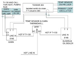
I have the new Garn plumbed...and this week I hope to flood and fire. Yeah! For controls, I plan to use a a419ABC to monitor the temp of the GARN, and if BELOW the setpoint, the a419 will energize the 8148 line supply...so a call for heat will burn oil. If the Garn is over 130, then the 8148 will not be energized by a separate relay will be, and therefore the call for heat will turn on the circulators around the Garn. In either case, the 363 will not be changed...so it just sends out the call for heat and removes it when satisfied. I just have to run the line power to the 8148 through the a419, run the TT input going to the oil boiler to an additional relay, and then power this relay from the "other contact" on the a419. Seems like a simple and cheap way to accomplish my needs. The 363 will keep managing the actual primary loop temp...without changing anything in its wiring.

Thanks to all!
 
bpirger said:
...

Is this TT input just a 24V AC input that closes a relay on the 8148?

...

The L8148A T-T terminals complete the circuit that energizes the 1K relay coil. The L8148A has its own 120VAC/24VAC transformer that supplies the power. So to have a call-for-heat what you need is a switch that will short the two T-T terminals together.

bpirger said:
I just have to run the line power to the 8148 through the a419, run the TT input going to the oil boiler to an additional relay, and then power this relay from the “other contact” on the a419.
A419ABC is SPDT. What's the 'other contact'?

Can't really get the whole picture here. A plumbing schematic would help a lot.

Cheers -ewd
 
Thanks EW! Now I understand. To drive the T T terminals, literally the external control is just a switch, i.e. a short across the T T terminals. This completes the circuit inside the 8148, closes the internal circulator relay (in the 8148) and fires the boiler (B1 B2), unless the aquastat reaches the high limit, then the boiler is not fired but the circulator keeps running.

So what I'm thinking I'd do:

1. Use the a419 to provide the line power to the oil boiler 8148, only if the temp in the Garn (measured by the a419) is below say 130. So without the line power, the boiler can't fire. Note that in my system, the primary loop circulator is controlled from the Tekmar 363. So I can power down the oil boiler 8148, if the Garn is warm, and keep the primary loop circulator running.

2. If the Garn is over 130, then the a419 will power the Garn controller. If the Garn is below 130, this controller will NOT be powered.

3. In the schematic, I show using another 8148 on the Garn side. If T>130, it is provided power (from the other contact off the a419...one to the oil boiler controller (NO), one to the garn controller(NC), and only one is powered at any given time).

4. This Garn controller has to recognize the call for heat. I'd like to run the two controllers (here I show two 8148s) with the T T inputs wired in parallel. So when the call comes in, whichever controller is powered up (depending on the Garn Temp) will heat my primary loop. With the Garn 8148, only the circulator relay is used, to run my two Garn 00R pumps (wired in parallel...and the 8148 has no problem driving this 2.5A max load).

My concern here is wiring the T T terminals in parallel. Will this cause trouble? It seems like it may, since completing the loop in one 8148 will bring this 24V power to the other....and that seems like a problem.

In my first post this morning, I was thinking that the T T pair was driven by 24V, not just a "short", so I thought I could just use another relay to drive the Garn pumps (if the a419 was sending power to that relay)! But since it is the isolated switch in the 363 driving the T T inputs, I need to have the equivalent of the 24V circuit in the 8148. There's likely a cheaper way...please feel free to point me in that direction!

So, will this work, or will wiring the two T T terminals in parallel cause a problem? It seems to me like it might be a problem....

I'm hoping to not have to use an aquastat with a bulb, hence the a419, as the distance from the garn thermowell to the controller position is likely to be at least a foot.

Thanks to all! Looking forward to first fire!
 

Attachments

  • controller_10NOV10.jpg
    controller_10NOV10.jpg
    67.4 KB · Views: 1,764
bpirger said:
Thanks EW! Now I understand. To drive the T T terminals, literally the external control is just a switch, i.e. a short across the T T terminals. This completes the circuit inside the 8148, closes the internal circulator relay (in the 8148) and fires the boiler (B1 B2), unless the aquastat reaches the high limit, then the boiler is not fired but the circulator keeps running.

So what I'm thinking I'd do:

1. Use the a419 to provide the line power to the oil boiler 8148, only if the temp in the Garn (measured by the a419) is below say 130. So without the line power, the boiler can't fire. Note that in my system, the primary loop circulator is controlled from the Tekmar 363. So I can power down the oil boiler 8148, if the Garn is warm, and keep the primary loop circulator running.
Oh I see, this was the missing piece of the puzzle.
2. If the Garn is over 130, then the a419 will power the Garn controller. If the Garn is below 130, this controller will NOT be powered.

3. In the schematic, I show using another 8148 on the Garn side. If T>130, it is provided power (from the other contact off the a419...one to the oil boiler controller (NO), one to the garn controller(NC), and only one is powered at any given time).
L8148A seems like overkill. Since you don't need the 44 ampere locked-rotor inrush, a normal 6-10 ampere ice-cube relay would do the trick. Plus you don't need the low-limit function since the A419 is supplying that function, plus you don't need the high-limit.
So, will this work, or will wiring the two T T terminals in parallel cause a problem? It seems to me like it might be a problem....

I honestly don't know, it's conceivable if the secondaries were in phase you could get away with it, but just because L1 and L2 are correctly wired to the primaries doesn't guarantee that the manufacturing process will keep the secondaries the same for all units produced. You could verify yourself, but now you're building a one-man system that your widow may not appreciate. Better to just get a double-throw relay and use it to implement two independent T-T closures.


4. This Garn controller has to recognize the call for heat. I'd like to run the two controllers (here I show two 8148s) with the T T inputs wired in parallel. So when the call comes in, whichever controller is powered up (depending on the Garn Temp) will heat my primary loop. With the Garn 8148, only the circulator relay is used, to run my two Garn 00R pumps (wired in parallel...and the 8148 has no problem driving this 2.5A max load).

...
There's likely a cheaper way...please feel free to point me in that direction!
To summarize my first pass suggestion would be to replace the Garm L8148 with one throw of a DPDT ice-cube relay, get another DPDT ice-cube relay to switch the call-for-heat closures in parallel, and scrounge up a small 120VAC/24VAC transformer to supply relay coil and control current power. Using the NC/NO from the aquastat to power the oil burner or the Garn sounds pretty slick.

As an alternative to ice-cube relays and building an enclosure and all that, there are some self-contained module relays that people mention here from time-to-time that might be nicer, but I can't remember what they're called. [Found it Functional Devices RIB relays. E.g.: RIB2401D. For one or two relays at $20 each doesn't sound bad at all compared to DIY.]
 
Thanks Eliot. As I was driving to work, I had thought about using a relay to switch the T T drive "line", so then I don't have to worry about any phasing issues. And I certainly agree the 8148 is not needed, as all I am using it for is the transformer setting up the T T terminal "turn on". Then again, if it is already to attach to the wall and connect a couple of lines..... But I'm sure there is something else that can do this simple function without all the frills of the 8148.

Thanks!
Bruce
 
Status
Not open for further replies.