TARM SOLO PLUS 40 LOW COMMON SUPPLY HEADER TX

  • Active since 1995, Hearth.com is THE place on the internet for free information and advice about wood stoves, pellet stoves and other energy saving equipment.

    We strive to provide opinions, articles, discussions and history related to Hearth Products and in a more general sense, energy issues.

    We promote the EFFICIENT, RESPONSIBLE, CLEAN and SAFE use of all fuels, whether renewable or fossil.
Status
Not open for further replies.

KenLockett

Minister of Fire
Dec 27, 2011
580
Eastern Upstate NY
HELLO EVERYONE,

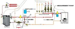
FINALLY THOUGHT I HAD THE SOLO 40 PLUS WORKING THE WAY I WANTED HOWEVER QUESTIONED THE RATE THAT THE HOUSE WAS HEATING UP USING THE WOOD BOILER VERSUS THE OIL FIRED BOILER. TO TEST MY CONCERN, I TOOK A MEASUREMENT AT THE POINT LABELED 'MEASUREMENT POINT' IN THE ATTACHED DIAGRAM BASED UPON THE FOLLOWING TWO SETS OF CONDITIONS:

(1) WITH WOOD BOILER COLD (HAD NOT BEEN RUN FOR MORE THAN 4 DAYS) AND THE SUPPLY AND RETURN TO THE WOOD BOILER ISOLATED (VALVES CLOSED ALTHOUGH NOT SHOWN IN THE ATTACHED DIAGRAM), THE OIL BOILER FIRED TO SETPOINT AND THE TEMPERATURE READING ON THE IR THERMOMETER READS APPROXIMATELY 180 DEGF (AT MEASUREMENT POINT) AND THE BOILER GAUGE READS APPROXIMATELY THE SAME (180-185 DEGF).

(2) WITH THE WOOD BOILER VALVED IN (ISOLATION VALVES OPEN) AND AT SETPOINT (188 DEGF), ACCORDING TO THE CONTROL PANEL GAUGE, AND DRAFT FAN OFF, THE IR THERMOMETER READS APPROXIMATELY 145-160 DEGF (AT MEASUREMENT POINT). AT THIS CONDITION AND SINCE I HAD JUST FIRED THE WOOD BOILER, THE OIL BOILER WAS STILL HOT AND STILL MEASURED APPROXIMATELY 180-185 DEGF ON THE BOILER GAUGE)

WHEN I FIRST SUSPECTED THE LOWER TX AT THE COMMON SUPPLY HEADER WITH WOOD BOILER OPERATING I SUSPECTED THAT THE SWING CHECK VALVE ON THE SUPPLY SIDE OF THE OIL BOILER WAS NOT SWINGING COMPLETELY CLOSED WITH WOOD BOILER CIRCULATOR IN OPERATION AND THAT COOL WATER FROM THE OIL BOILER WAS BEING 'STRIPPED' INTO THE HOT WATER SUPPLY STREAM WHEN OPERATING AT TX WITH THE WOOD BOILER. THE OBSERVATIONS AS DESCRIBED ABOVE WOULD TEND TO CONTRADICT THIS THEORY AS THE OIL BOILER WAS STILL AT OPERATING TX FROM THE PRIOR OPERATION.

OK, MY NEXT THEORY WAS THAT MAYBE THE GAUGE ON THE CONTROL PANEL OF THE WOOD FIRED BOILER WAS NOT ACCURATE (I.E. ACTUAL TX ONLY 160 DEGF WHEN GAUGE READING 180-185 DEGF). TO TEST THIS, WITH THE WOOD BOILER AT TX SETPOINT OF 185 DEGF, I DIALED THE OVERTEMP AQUASTATE BACK BELOW 150 DEGF THEN SLOWLY ADJUSTED THE SETTING UNTIL THE CONTACT CLOSED ON RISING TEMP AND ON THE AQUASTAT THIS OCCURED AT APPROXIMATELY 187 DEGF. THEREFORE, I HAVE TO ASSUME THE GAUGE ON THE BOILER IS CORRECT.

AT THIS POINT I SUSPECT THIS HAS SOMETHING TO DO WITH THE TERMOVAR MIXING VALVE. I AM ALMOST 100% SURE I HAVE THIS PLUMBED CORRECTLY. AS A MATTER OF FACT, WHEN I RECEIVED THE TERMOVAR FROM BIOMASS USA SOMEONE HAD EVEN GONE TO THE TROUBLE OF MARKING THE PORTS WITH A BLACK MARKER THAT I BELIEVE I HAD VERIFIED AGAINST THE VALVE OEM LABELING. IN ADDITION, THE BALANCING VALVE ON THE PORT 1 SIDE IS SET AT 45 DEGREES AS RECOMMENDED BY TARM ALTHOUGH THERE IS NO CLEAR REASONING WHY IT SHOULD BE SET AT THIS POSITION. THE WAY THE MANUAL EXPLAINS THE OPERATION OF THIS MIXING VALVE IS THAT AT 160 DEGF (72 DEGC) AND RISING, PORT 2 OF THE TERMOVAR BEGINS TO OPEN AND PORT 1 BEGINS TO CLOSE WITH PORT 2 REACHING THE FULL OPEN POSITION WHEN THE TX IS AT 172 DEGF. MANUAL DOES NOT STATE IF PORT 1 COMPLETELY CLOSES OR NOT BUT I ASSUME IT IS NEAR CLOSED POSITION. PORT 3 IS ALWAYS OPEN. ONE HYPOTHESES I HAVE IS THAT EITHER PORT ONE IS NOT CLOSING AT ALL OR THAT PORT 2 (FROM RETURN HEADER) IS LEAKING BACK INTO PORT 1 AND THE HOT WATER SUPPLY FROM THE MIXING VALVE IS BEING TEMPERED INCORRECTLY. HAVE CONSIDERED CLOSING THE BALANCING VALVE COMPLETELY AT OPERATING TEMP (AT WHICH POINT I BELIEVE RISK OF SHOCKING BOILER WITH RETURN WATER BELOW 140 DEGF IS MINIMAL) TO ESSENTIALLY ISOLATE THE MIXING PORTS UNLESS INTERNALLY THEY ARE SCREWED UP.

I AM USING A GRUNDFOS 3-SPEED CIRCULATOR ON MEDIUM SPEED AND MY ACTUAL NUMBER OF HEATING ZONES IS TWO UNLIKE THE DIAGRAM THAT SHOWS THREE. I AM NOT USING THE TERMOVAR LOADING UNIT WITH BUILT-IN CICRULATOR AND BALANCING VALVE.

DOES ANYONE HERE IN THE FORUM HAVE ANY SUGGESTIONS AND/OR INSIGHT INTO ABOVE OBSERVATIONS. ANY HELP WOULD BE MUCH APPRECIATED. YOUR INPUT HELPED SOLVE MY 'KETTLING' PROBLEM AND I'M HOPING THAT YOUR INSIGHTS WILL HELP ME GET BEYOND THIS ISSUE AND GET THIS THING WORKING IN AN OPTIMUM MANNER BEFORE THE REAL COLD SETS IN HERE IN THE NORTHEAST.

THANKS,
KEN
 

Attachments

  • SOLO PLUS PLUMBING 1.jpg
    SOLO PLUS PLUMBING 1.jpg
    29.5 KB · Views: 553
My wife has just informed me that it is not proper etiquette to use all CAPS when posting or texting. I of course did not know this so appologize ahead of time!

Ken
 
KenLockett said:
My wife has just informed me that it is not proper etiquette to use all CAPS when posting or texting. I of course did not know this so appologize ahead of time!
Tell her we appreciate it, that's pretty cool!

I'd suggest for starters, turn off or isolate all the load circuits and then gradually close down the balancing valve and see if you can force flow around the main loop. This would prove that all the check valves are working right and the boiler circ is working, but only if the mixing valve will flow a little at least when forced to.

Keep studying temperatures with your IR gun. Maybe listen to the mixing valve and the balancing valve with a big screwdriver and see if you can figure out what's going on inside.

As you suggest, so far everything points to the mixing valve.

Cheers --ewd
 
Good Morning Ken.

Are there any deviations in your system from the above diagram? Any flow checks that were or werent installed? Can you tell us what the temp of your oil boiler is several hours after you fire the wood? (meaning, after the oil would have had time to cool) Just want to make sure the oil boiler cools after you fire the wood boiler.

What are the temps in and out of your boiler using the IR gun? If you can measure around the piping close to the boiler, you can figure out where the flow is going. I agree with EWD above, its probably the mixing valve. Once you get your boiler up to temp, try closing the ball valve on Port 1 a little bit more.

Also, when does your circ 3-a cycle? Does it always run when there is wood in the boiler (which I would assume) or does it only kick on when there is a call for heat from the system?
 
Clarkbug said:
Good Morning Ken.

Are there any deviations in your system from the above diagram? Any flow checks that were or werent installed? Can you tell us what the temp of your oil boiler is several hours after you fire the wood? (meaning, after the oil would have had time to cool) Just want to make sure the oil boiler cools after you fire the wood boiler.

What are the temps in and out of your boiler using the IR gun? If you can measure around the piping close to the boiler, you can figure out where the flow is going. I agree with EWD above, its probably the mixing valve. Once you get your boiler up to temp, try closing the ball valve on Port 1 a little bit more.

Also, when does your circ 3-a cycle? Does it always run when there is wood in the boiler (which I would assume) or does it only kick on when there is a call for heat from the system?

Clarkbug,

Basically, it is plumbed as in the previous diagram with the exception of the location of the circulators relative to the baseboard heating and the fact that I only have two zones. Additionally I added to isolation valves on the supply and return headers to allow me to isolate the two boilers. All check valves of same type and location as in diagram and recommended by Tarm. I have attached a section of the plumbing diagram I created for the installation that shows the difference.

Yes, after the wood boiler has been firing at operating temp above aquastat setting that controls oil boiler burner interlock, the oil boiler eventually cools with the oil boiler gauge eventually falling to low limit on gauge (Maybe 110 DegF?).

On the black iron tee at supply header interestingly enough temp was approximately 165 DegF. This is what led me to believe that the gauge was incorrect. In hindsight, perhaps I should have covered the black iron fitting with masking tape as I did the shiny copper. Didn't think the emmissivity with the IR thermometer would have been an issue with the flat black iron surface but maybe not the case.

Circulator 3-A operates via aquastat (Tx only) to turn on (Contact closes to energize circulator) when Boiler Tx above 160 DegF while Oil Boiler Burner interlocked out (Contact opens interrupting power to oil burner) via another aquastat when Boiler Tx above 160 DegF.

Am going to fire the wood boiler again this morning and try to slowly throttle down on balance valve (port 1) when at tx setpoint as EWD suggested to see if the supply header Tx is influenced. Will also take some more measurements relative to the supply and return piping at wood boiler. This is difficult at this point as all copper 1 1/4" piping is completely insulated.

Thanks for the suggestions. Will let you know what I find.

Ken
 

Attachments

  • Solo Plus Plumbing Actual.jpg
    Solo Plus Plumbing Actual.jpg
    26.5 KB · Views: 369
Thanks for the great description Ken.

The fact that the temp is high at the outlet of the boiler but is ~20 degrees lower at the supply header tee (Im assuming its the tee in your above schematic, not the tee above the Danfoss valve) is further evidence that throttling the ball valve is the ticket.

As an aside, in the diagram above your indirect hot water heater appears to only be controlled by the oil boiler. Can you heat your DHW with the wood boiler also?
 
Clarkbug said:
Thanks for the great description Ken.

The fact that the temp is high at the outlet of the boiler but is ~20 degrees lower at the supply header tee (Im assuming its the tee in your above schematic, not the tee above the Danfoss valve) is further evidence that throttling the ball valve is the ticket.

As an aside, in the diagram above your indirect hot water heater appears to only be controlled by the oil boiler. Can you heat your DHW with the wood boiler also?

Clarkbug,

Attached below is the full plumbing schematic. DHW hot water supply controlled by it's own circulator that pulls from the common header. Boiler interlock aquastat simply interrupts burner circuit. Everything electrically operates same as with Oil Boiler when heating with wood boiler.

Just fired wood boiler and it is heating. Weighted check valve and black iron tee at wood boiler supply header currently reading 165 DegF but only 120 DegF at shared supply header (my Measured Point in first post). I think what is happening is that until Port 1 closes down (or until a greater restriction is placed at the port 1 via balance valve) there is not enough head to 'pop' the weighted check valve and allow flow to shared header. I will keep my progress posted as I continue to heat up.

Ken
 

Attachments

  • SOLO PLUS PLUMBING FULL.jpg
    SOLO PLUS PLUMBING FULL.jpg
    84.2 KB · Views: 355
Ok, wood boiler is now at Tx SP (185-190 DegF on wood boiler control panel gauge). I hit the weighted check valve with the IR and it reads approximately 180 DegF. I hit the black iron tee on wood boiler supply header (tan masking tape on this) and it reads approximately 180 DegF. I hit the red flow check on the heating zone that is calling and I'm reading around 177 DegF. The header pipe is reading only around 160 DegF. I have tan masking tape on the copper header pipe while the weighted check valve is flat grey/blue while the heating zone flow check is flat red.

Reason I wasn't getting Tx on previous post I think was not because the weighted check did not pop but because neither zone was calling to pull the heated flow into zones!!!???.

Perhaps my whole issue here is with IR thermometer emmissivity issues?? Only thing I'm not sure of is deviation from gauge to IR reading at weighted check valve (7-10 DegF deviation) and deviation between weighted check valve and heating zone flow check (3 DegF deviation). Perhaps the whole issue is with a result of inaccuracies in my measurements based upon analog gauges and IR thermometers. Ugh!!

I am a controls engineer by training and am used to precise measurements based upon in-situ electronic instrumentation. I gotta start looking at the less obvious things. By the way, throttling of the balance valve to the closed position made no difference on the measurements.

Ken
 
lots of cases of faulty readings on temp and psi gauges. I Know it made me do some figuring to find the faulty ones.
 
I would say you want the same color tape on everything if you can help it. What is the ratio on your temp gun? Just wanting to make sure you are getting the temps at the right spot, not something else.

I know that I had issues with the IR when trying to pinpoint things, so I ended up getting some wired temp sensors and displays from eBay (after reading stuff from EWD and jebatty). You may want to look into the cheap solution of taping some frothing/candy thermometers to your piping to troubleshoot, or get a good thermocouple and reader, and move that around.

Also, can you prop your weighted check open for a bit to see if that helps things? Some have a manual override.

Controls engineer as in like Siemens, JCI, or TAC controls? Or more stuff based on industrial level controls? (Just curious here)
 
I followed the same diagram from tarm in your first post. And had the same initial problem. It took a few firings before I got everything flowing smoothly.

For me I had some air trapped in the high points of the piping that was causing intermittent issues with the pumps. Once I got it all out everything has worked great since. Didn't help that I had to drain and refill several times for the boiler pre treatment and conditioner.

For the bypass I choked the pipe down to 1.25" and have a gate valve set at about 20 %. Hard to tell exactly since I didn't use a ball valve.

I also have it best to leave the pump on setting 2. But if the whole system is cold I set it high for a hour or two.
 
Clarkbug said:
I would say you want the same color tape on everything if you can help it. What is the ratio on your temp gun? Just wanting to make sure you are getting the temps at the right spot, not something else.

I know that I had issues with the IR when trying to pinpoint things, so I ended up getting some wired temp sensors and displays from eBay (after reading stuff from EWD and jebatty). You may want to look into the cheap solution of taping some frothing/candy thermometers to your piping to troubleshoot, or get a good thermocouple and reader, and move that around.

Also, can you prop your weighted check open for a bit to see if that helps things? Some have a manual override.

Controls engineer as in like Siemens, JCI, or TAC controls? Or more stuff based on industrial level controls? (Just curious here)

Clarkbug,

I am a lead controls/project engineer for Emerson Process Management Power and Water Solutions combustion turbine division (Ovation DCS) for past four years. Prior to that self-employed for 7 years primarily in PLC based controls.

Ratio of my gun is D:S = 8:1. Got an inexpensive one on Amazon ($16) and have a Klein ($89) from Home Depot. Klein is a little more fancy, heavier, and stable but they essentially read the same within a couple of degrees. Have tried the blue painters tape, thick black masking tape, and thin tan masking tape. All taping seems to yield a somewhat erratic signal. Measurements on the non-shiny metallic surfaces as I mentioned previously yield a very stable signal. I try to get as close as possible to the surface using the laser pointer to more precisely pinpoint the area I am measuring. Is this the way you do it.

The weighted flow check (Taco) does appear to possibly have a manual override on top (knurled knob). Wouldn't it be nice if the check valves all had some type of mechanical position/flapper feedback?

Can you point me to a specific link for the wired temp sensors and displays you mention above. I actually bought a probe type thermocouple meter for measuring flue temps. After seeing an earlier thread pertaining to the Condar Tx probe and it inaccuracies (distributed by Tarm Biomass USA) I bought the meter to indeed confirm my flue temps were not 900-1000 DegF and instead 450-650 DegF. Condar actually sent me a newer model probe that indeed does seem to be more accurate.

Thanks,
Ken
 
mikefrommaine said:
I followed the same diagram from tarm in your first post. And had the same initial problem. It took a few firings before I got everything flowing smoothly.

For me I had some air trapped in the high points of the piping that was causing intermittent issues with the pumps. Once I got it all out everything has worked great since. Didn't help that I had to drain and refill several times for the boiler pre treatment and conditioner.

For the bypass I choked the pipe down to 1.25" and have a gate valve set at about 20 %. Hard to tell exactly since I didn't use a ball valve.

I also have it best to leave the pump on setting 2. But if the whole system is cold I set it high for a hour or two.

Mike I too had air trapped in my system. Per a recommendation in a post from another thread I added an auto-bleed vent valve at the top of the boiler in place of the original manual bleed valve. A good air separator and the auto-bleed valve on the wood boiler, an air scoop and auto-bleed on the oil side, along with a very thorough purge of the system a couple of weeks ago I believe has taken care of the trapped air I believe I had in my system. I actually thought I heard air in the sytem around the boiler piping this morning. Hope this is not the case. My thought is the air-separator and auto-bleed at the high points of the boiler should take care of small pockets over time. Otherwise why else would they be needed.

Have been thinking about pre-treatment and conditioner but not really sure if the trouble of doing it now versus the long term benefits are worth it. What is your opinion.

Also, do you know if it is a good idea to change the pump speed while the pump is operating? I read somewhere in the forum a while back that this is not a good idea.

Thanks,
Ken
 
KenLockett said:
Clarkbug,

I am a lead controls/project engineer for Emerson Process Management Power and Water Solutions combustion turbine division (Ovation DCS) for past four years. Prior to that self-employed for 7 years primarily in PLC based controls.

Ratio of my gun is D:S = 8:1. Got an inexpensive one on Amazon ($16) and have a Klein ($89) from Home Depot. Klein is a little more fancy, heavier, and stable but they essentially read the same within a couple of degrees. Have tried the blue painters tape, thick black masking tape, and thin tan masking tape. All taping seems to yield a somewhat erratic signal. Measurements on the non-shiny metallic surfaces as I mentioned previously yield a very stable signal. I try to get as close as possible to the surface using the laser pointer to more precisely pinpoint the area I am measuring. Is this the way you do it.

The weighted flow check (Taco) does appear to possibly have a manual override on top (knurled knob). Wouldn't it be nice if the check valves all had some type of mechanical position/flapper feedback?

Can you point me to a specific link for the wired temp sensors and displays you mention above. I actually bought a probe type thermocouple meter for measuring flue temps. After seeing an earlier thread pertaining to the Condar Tx probe and it inaccuracies (distributed by Tarm Biomass USA) I bought the meter to indeed confirm my flue temps were not 900-1000 DegF and instead 450-650 DegF. Condar actually sent me a newer model probe that indeed does seem to be more accurate.

Thanks,
Ken

Ken,

Here is what I am using to measure my boiler outlet temps, tank temps, and temps to the house zones.

http://www.ebay.com/itm/Auto-Car-Me...671?pt=LH_DefaultDomain_0&hash=item519cdfc90f

I have the probes adhered with the HVAC duct tape that is actually an aluminum foil per the advice of jebatty here, and it seems to work great. I put some thermal grease from radio shack around them to make sure there is good contact, and they have worked well. I used a wall wort transformer that I had kicking around to provide power. They make a red and a blue version, so I just use red for hot, blue for cold.

If you shop around for something other than the link above, make sure you get the "digital' version of the meter (SP-334). The other (slightly cheaper) versions have a very wide range for accuracy, which wont be of much use to you.

If you have a TACO flow check, that is indeed an override. Twist that knob and you will lift the weight, and get flow all the time.

The IR gun that I used was borrowed from my office and has two dots on it to show the circle of measurement. I got fairly close to my piping, but only really used it on my initial system startup to make sure things were working properly.
 
"Do you know if it is a good idea to change the pump speed while the pump is operating?"

I hope it's ok because I've did it a lot. Yes you should treat the water. Why spend all that time and money and skimp on the protection ?
 
woodsmaster said:
"Do you know if it is a good idea to change the pump speed while the pump is operating?"

I hope it's ok because I've did it a lot. Yes you should treat the water. Why spend all that time and money and skimp on the protection ?

Can anyone recommend specifically what chemicals (i.e. brand, manufacturer, etc.) they use to treat the water and the method for adding to the boiler? To fill my boiler I initially hooked a hose to the drain valve and backfilled from the bottom up. Any subsequent bleeding I have done since I open the drain and allow the boiler to auto-fill from the feedwater override on the pressure regulator. Not sure how one one add/mix the treatment into the water.
 
Clarkbug said:
KenLockett said:
Clarkbug,

I am a lead controls/project engineer for Emerson Process Management Power and Water Solutions combustion turbine division (Ovation DCS) for past four years. Prior to that self-employed for 7 years primarily in PLC based controls.

Ratio of my gun is D:S = 8:1. Got an inexpensive one on Amazon ($16) and have a Klein ($89) from Home Depot. Klein is a little more fancy, heavier, and stable but they essentially read the same within a couple of degrees. Have tried the blue painters tape, thick black masking tape, and thin tan masking tape. All taping seems to yield a somewhat erratic signal. Measurements on the non-shiny metallic surfaces as I mentioned previously yield a very stable signal. I try to get as close as possible to the surface using the laser pointer to more precisely pinpoint the area I am measuring. Is this the way you do it.

The weighted flow check (Taco) does appear to possibly have a manual override on top (knurled knob). Wouldn't it be nice if the check valves all had some type of mechanical position/flapper feedback?

Can you point me to a specific link for the wired temp sensors and displays you mention above. I actually bought a probe type thermocouple meter for measuring flue temps. After seeing an earlier thread pertaining to the Condar Tx probe and it inaccuracies (distributed by Tarm Biomass USA) I bought the meter to indeed confirm my flue temps were not 900-1000 DegF and instead 450-650 DegF. Condar actually sent me a newer model probe that indeed does seem to be more accurate.

Thanks,
Ken

Ken,

Here is what I am using to measure my boiler outlet temps, tank temps, and temps to the house zones.

http://www.ebay.com/itm/Auto-Car-Me...671?pt=LH_DefaultDomain_0&hash=item519cdfc90f

I have the probes adhered with the HVAC duct tape that is actually an aluminum foil per the advice of jebatty here, and it seems to work great. I put some thermal grease from radio shack around them to make sure there is good contact, and they have worked well. I used a wall wort transformer that I had kicking around to provide power. They make a red and a blue version, so I just use red for hot, blue for cold.

If you shop around for something other than the link above, make sure you get the "digital' version of the meter (SP-334). The other (slightly cheaper) versions have a very wide range for accuracy, which wont be of much use to you.

If you have a TACO flow check, that is indeed an override. Twist that knob and you will lift the weight, and get flow all the time.

The IR gun that I used was borrowed from my office and has two dots on it to show the circle of measurement. I got fairly close to my piping, but only really used it on my initial system startup to make sure things were working properly.

Clarkbug,

How does the probe connect to the LED display? Do you foil tape the probe to the piping them remotely mount the display at the same location you provide power? What is the lead length if you indeed mount in this manner? The pictures I have found just show the display. If it's not too much trouble and if you get a free moment any chance you could send a photograph or two of how you have installed?

Thanks
 
KenLockett said:
How does the probe connect to the LED display?
In the ebay listing above they show a photo of the back of the display. Two pins on the left are power. Then there's two three-pin connectors for probes. One or two probes can be connected. With two probes you have to set it up to display the two probe temperatures alternately, which sucks, so usually only one probe is connected.

It's hard to see but both the power leads and the probe leads have white plastic connectors that plug into the back of the display.
Do you foil tape the probe to the piping them remotely mount the display at the same location you provide power?
Yes.
What is the lead length if you indeed mount in this manner?

Most have a one meter lead. The leads can be extended with high quality low capacitance cable up to ten meters that I know of. In my experience some units require a pull-up resistor to make the extended cables work.
 
Clarkbug said:
I think EWD took care of most of your questions Ken, but if you have any others, feel free to ask.

Pics of how I have mine installed are here:

https://www.hearth.com/econtent/index.php/forums/viewthread/88003/

Nice, I hadn't seen the IR photos before!

I see you found some DS18B20 sensors with 3 meter leads. Haven't seen those before, saves a lot of screwing around extending leads in most cases, I would think.

--ewd
 
Thanks!

I stole it from my office just to take neat pictures, and to try and balance out how the flow was through the tanks if I had to. Based on the images, I think they load/unload close enough for me.

All of the sensors that I bought are the ones that came from Sure Electronics, so the lead lengths are just what they shipped me.
 
Status
Not open for further replies.