The Tarm Has Landed - Again: the move into the new shop

  • Active since 1995, Hearth.com is THE place on the internet for free information and advice about wood stoves, pellet stoves and other energy saving equipment.

    We strive to provide opinions, articles, discussions and history related to Hearth Products and in a more general sense, energy issues.

    We promote the EFFICIENT, RESPONSIBLE, CLEAN and SAFE use of all fuels, whether renewable or fossil.
Status
Not open for further replies.

jebatty

Minister of Fire
Jan 1, 2008
5,796
Northern MN
In December 2009 the shop was built, and finish work started in March 2010. First the pictures, then comments.

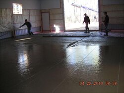
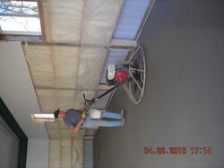
The concrete pour and concrete finishing. I hired a local mason for this work.

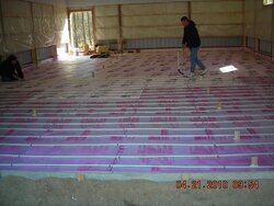
Next the pex install and radiant install. Again, I hired a local professional to do this for me.

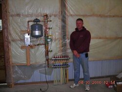
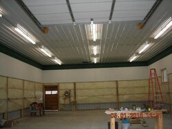
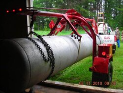
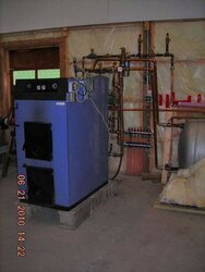
The shop was then ready for the boiler and moving the 1000 gal storage tank. The LP gas company from whom I bought the tank moved it for free – a 1-1/2 mile trip from my old shop. The mason moved the boiler for me.

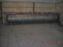
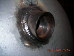
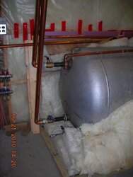
I neighbor who is a welder by trade welded into the tank 2 - 2" fittings. A darn good job.

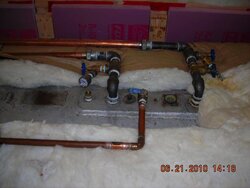
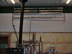
My plumbing design is to have the boiler feed the tank directly, with 1-1/4" boiler lines going to the new 2" fittings. The top supply fitting has a 1-1/4" pipe on the inside extending 18" horizontally just below the top of the tank. The bottom fitting is for boiler return. Past experience is that the hot water from the boiler stays at the top of the tank, gradually moving down as the whole tank is loaded with hot water. Right now I have a Taco 007 on this very short boiler/tank loop, and I will wait and see how well it handles boiler output as tank temperature climbs above 170F on its way to 190F.

The radiant floor supply draws from the top of the tank and returns via a dip tube to the bottom of the tank. These fittings are 1" and are about 6 feet from the supply/return end of the tank. The supply goes to Side A of a plate heat exchanger and is isolated from Side B for the in-floor pex. I have a Taco 007 on this short loop.

The Side B in-floor pex side of the heat exchanger has anti-freeze, thus the reason for the plate heat exchanger. Six loops of pex, each about 270' of 1/2" pex, 1600 feet total. The shop floor is 32' x 48'. I have a Taco 009 on the Side B in-floor pex side of the heat exchanger.

I also stubbed out fittings to add a unit heater to give a heat boost when needed. I have the unit heater, but have not yet installed it. And stubs out for the over-heat loop which will be installed on the wall above the tank.

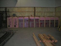
The tank is boxed in with 2" foam on the perimeter and stuffed with fiberglass; about R30 all the way around.

There is a 4 foot wide rear access door in the building to bring wood in to keep the Tarm doing its job. I have cleared space behind the building to store 10-20 cords of wood. My guess right now is that I will use about 4 cords each winter of mixed pine, aspen and some birch.

Still to do: install the chimney and the overheat loop, and finish the monitor/control system.

The control system will be quite simple. Basically an aquastat or equivalent to control the boiler circulator: ON at boiler supply of 165F, off at 160F. The Tarm itself shuts down at about 190F, back on at about 180F. The sole purpose of the boiler is to bring the 1000 gal tank up to about 190F and then “rest,” while the radiant floor gets its 120F water via a mixing valve. I will have about 575,000 stored BTU’s if I bring the entire tank up to 190F.

A similar control for the radiant floor. I placed a pex stub into the concrete to take a sensor to control the floor heat. I will have to experiment a bit to see what the best floor temperature should be, maybe 55 - 60F? Maybe an outdoor reset controller? When the radiant floor is ON, the circs on each side of the heat exchanger will be ON. I likely will use a line voltage thermostat for the unit heater to provide a heat boost when and if needed.

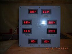
I also will be adding a number of sensors to provide interesting data logging and keep me busy during the long, cold, dark Minnesota winter nights, as well as submitting posts to Hearth.com to bother all of you. Sensors for the boiler HWS, boiler HWR, boiler stack; sides A and B of the heat exchanger; unit heater HWS and HWR; tank top, 1/3 down from top, 2/3 down from top, and tank bottom; floor temperature; building inside temperature and outside temperature. Many of these sensors also will feed digital panel meters so at a glance I can get a read-out of total system status.

It would have been great to also have flow meters on the boiler loop, tank loop, and floor loop, but the extra plumbing and cost, as well as added pump head, ruled these out. Flow meters along with delta-T would give accurate BTUH performance data. Now I will have to calculate BTUH performance the old fashioned way.
 

Attachments

  • 1-Concrete Pour.jpg
    1-Concrete Pour.jpg
    47.5 KB · Views: 945
  • 2-Concrete Finish.jpg
    2-Concrete Finish.jpg
    32.4 KB · Views: 969
  • 3-Pex Install.jpg
    3-Pex Install.jpg
    50.3 KB · Views: 1,023
  • 4-Radiant Install-1.jpg
    4-Radiant Install-1.jpg
    42.9 KB · Views: 1,075
  • 5-Ready for Boiler.jpg
    5-Ready for Boiler.jpg
    44.6 KB · Views: 946
  • 6-Tank Move.jpg
    6-Tank Move.jpg
    65.3 KB · Views: 957
  • 7-Tank in Position-1.jpg
    7-Tank in Position-1.jpg
    28.9 KB · Views: 934
  • 8-Weld Fitting.jpg
    8-Weld Fitting.jpg
    28.7 KB · Views: 969
[continued]

Here are the installed fittings on the top of the tank and on the end; also the complete tank; and the finished job.

I finished wiring in the main monitor panel. Sensors for the stack and radiant are not yet hooked up. I also will be installing a bunch of sensors for data logging.

The inside of the shop walls will be finished with vertical 1" white pine boards, rough sawn, all from trees on our land. I have these on hand and ready to go.
 

Attachments

  • 9-Top of Tank Fittings.jpg
    9-Top of Tank Fittings.jpg
    39.5 KB · Views: 956
  • 10-End of Tank Fittings-1.jpg
    10-End of Tank Fittings-1.jpg
    40.6 KB · Views: 957
  • 11-Tank Complete-1.jpg
    11-Tank Complete-1.jpg
    30.9 KB · Views: 970
  • 13-Install Complete-1.jpg
    13-Install Complete-1.jpg
    37.9 KB · Views: 1,034
  • 12-Monitor Panel.jpg
    12-Monitor Panel.jpg
    30.9 KB · Views: 941
Looks awesome. I'm extremely jealous of your shop....
 
Very, very nice. I really like the steel on the ceiling. Your going to have a great system.
 
Nice setup! I am jealous also... I have a few questions for you. I am currently installing a tank very similar to yours.

1. Why are you using a HEX as opposed to pressurized storage. *** I see you are doing this because of the in floor pex*** Is that the only reason? How much efficiency do you think you loose not being pressurized?

2. What type of fitting did you use to be able to extend pipes into the tank?


Thanks!
 
I just read your OP again. Seems like the tank itself is pressurized? But I didn't see an expansion tank in the pics...
 
Thanks for the generous comments.

The tank is pressurized but the big expansion tank (SX-160V Extrol) is behind the boiler and can't be seen. The boiler, 1000 gal tank, loop to Side A of the HX, the loop to the unit heater, and the overheat loop all are served by this expansion tank.

The 2" fittings welded into the tank are black steel (not cast) threaded couplings. To extend the pipe into the tank, I first used a 2" to 1-1/4" reducing bushing to screw into the 2" fitting. Before screwing this in I welded an 18" piece of 1-1/4 black steel pipe into the back side of the 2" bushing. I then screwed a 1-1/4" x 6" nipple into the front side of the bushing, and with that added leverage screwed the bushing with the 18" x 1-1/4" extension into the 2" coupling.
 
Very nice!

I am curious to hear how the taco 007 works. We're using the termovar loading unit on the froling here... it's a grundfos 15-58 (three speed) so the pump curve is similar. Once the return temps start to get up around 160 the froling begins to modulate down to keep from overshooting the setpoint. We have about 7 or 8 feet of head from the boiler to the tanks. Actually turning the pump to the slowest setting works a little better for charging storage... reducing the GPM increases delta T, so you end up sending warmer water to the tops of your tank all in one shot. My issue here is that some of the return water from the zones heads back to the boiler thereby increasing the return temp... this pushes the boiler to modulate down pretty low when the termovar is on low, so I just keep the pump on high during the heating season and life's good.

My guess is that the 007 will perform well. Especially considering that once the return from the tank starts to rise the wood load will have mostly been used up and the output of the boiler will have dropped substantially... fewer btus of output means that the requirement for gpm's may not rise as the delta t between the bottom of the tank and the boiler diminishes. I am sure that once you get to tinkering with the system, you'll be able to get a feel for it.

Again, very nice setup... enjoy.

cheers.
 
Piker: I have a 15-58 which I may substitute for the boiler 007. I agree that the slower circ setting may be best for quickly providing the hottest water to the top of the tank with the least mixing. This may the way to go especially when top of tank temp gets quite low (close to 120F) and a heat boost is needed from the unit heater, which may need the hotter water to provide good heat without feeling a cool draft.

Higher boiler return temps only become an issue when return rises above 150-160F, as the Termovar provides return water protection to the boiler within that range. I suspect that I will experience some tank mixing resulting from Side A HX radiant return going to the bottom of the tank, although there is about 6' separation between this return point and the boiler return from the tank. I have sensors on the far end of the tank (top, down 12", down 24", bottom), and I think I also should put sensors on the boiler return end of the tank in the same positions. Comparing these two sets of readings should evidence the amount of mixing that takes place in the tank, as a flow loop may develop between tank supply and tank return. When I start to see the data I also will start experimenting with flow rates with the goal of minimizing tank mixing, if it becomes significant.

I've had a lot of fun these last two heating seasons with data collection and experimenting, and now that fun will begin again with a totally new setup and different operating conditions. I can see that my current 4 channel data recorder will not be sufficient, and I'm going to start looking to expand that considerably so that I can get same time data from more sensor locations.
 
Jebatty, Beautiful design and layout. Add me to the envious list. It must have be fun designing a new-build from scratch with all the features that make the wood heat work best. My only comment is that the Solo 40 looks small in that big shop! Will it put out enough BTU/hr to keep up with your cold MN winters?
 
I estimate heat loss at 40-50,000 BTUH; and that's with -30F extreme outside temp. That extreme applies for about 10-20 days each winter. Average coldest average winter temp in this area is -3F in January. The Tarm is rated at 140,000 BTUH, and from past experience I estimate average output over a burn cycle of about 100,000 BTUH. I think I feel safe in saying that the Tarm has plenty of capacity to keep the shop warm.

Hard to say this, but I'm a bit excited to fire it up to see how radiant floor really works. Normally, Sept is the first time we need heat, and May and sometimes early June is the last time heat is needed.
 
The Tarm system now is active. On July 9 I punched through the ribbed steel roof for the chimney and finished the chimney install. Kind of a puzzle to cut and bend the roof flashing to fit over the ribbed steel roof, but got it done and then sealed it with butyl rubber caulking. Total chimney height is 21', including 9' of black steel on the inside to the ceiling and then 12' of Class A. Then I filled the system with about 1075 gallons of cold 51F well water which I pressurized to 20 psi. A couple of very small leaks at unions, which after tightening quickly sealed. No leaks at threaded or soldered joints. I've gotten much better at doing these. While the tank was filling I installed the control for the boiler/tank loop and added a couple of temporary monitoring sensors so I could check tank top and bottom temperatures at both ends of the 19' tank and make a rough determination as to stratification or mixing.

The condensation caused by the cold water meant that the Tarm had to be fired, which I did on July 10. I heated the tank to 140F top, bottom was still 51F on both ends, although top at the fill end was 4F higher than top at the opposite end 19' away. No internal loop between the fill and return was evidenced. I then continued to run the circulator to achieve some mixing of the tank water. This morning the top was 127F and the bottom was 64F. That should evaporate out all the condensation water collected in the insulation.

I didn't run the infloor. That will have to wait until colder weather. And I still have to install the overheat loop and the unit heater, both stubbed in with shut-off valves.

Later today I will add 6 gallons of boiler chemical and then fire the boiler once more to mix the chemical well through the tank and boiler. The easy way I found to do this included putting a shut-off valve on the expansion tank. With the system pressurized to 20 psi and at the end of the firing yesterday, I shut-off the valve on the expansion tank to trap the pressurized water. Now as the tank gradually cools tank pressure drops quickly. I will have to drain some additional water from the tank to take the extra 6 gallons, and when this is added, I will open the shut-off valve on the expansion tank, the pressurized water will now again pressurized the entire system. Might have to add some additional water. Regardless, this is an easy way to de-pressurize a pressurized system without draining a lot of water.

It's hard to think about the heating season on July 11, but now the Tarm and I are ready and we both are even excited to see the performance of the in-floor.
 
Jebatty,
You keep putting up photos of that beatiful shop on the internet with the large door opening, in floor heat, and allot of floor space, your going to have all of your neighbors coming over with all of their equipment needing rebuilt during the cold winter begging for space to rent.
 
I almost feel sad -- plumbing is done on the Tarm landing. Yesterday I installed the overheat loop and then added 6 gallons of boiler chemical and again fired the Tarm to circulate everything well. The stubs on the overheat loop that show in the picture have no useful purpose. I reuse lots of copper when possible, and those pieces were cut from other plumbing of years past with capped off old branch lines. Install of the unit heater will wait until I have the wall done, and may even wait until winter to see if I really need it. Then again, it might look good sitting high on the wall keeping watch over everything.

By observation I'm fairly impressed by how easy it was to heat the tank (top to 160F and bottom at 110F) with so little wood, and low heat value aspen was the wood of choice. Flue temp was in the 330-380F range. The ample insulation on the tank makes a big difference in heating the tank.

Unless something unusual comes up, or to answer a question, this is my last post on the Tarm landing. During winter I will report data results, which might be of added interest as the new data can be compared with data collected last year.

¡Hasta luego, hasta pronto!
 

Attachments

  • DSCN1704-1.jpg
    DSCN1704-1.jpg
    25.9 KB · Views: 621
Think how nice a Garn would of looked in that space! :p Just think, no over heat loop along with half of that plumbing, horz. exhaust, Etc. I know, I know, not pressurized. Congrats J, looks like an awesome shop!
 
The Garn could look nice, but the blue Tarm is so mellow. lol. Before I bought the Tarm, I considered a Garn, but I decided against the Garn because of the possibility of having to move the system in the future. The future came true, and it was quite easy to uninstall, move, and reinstall the Tarm. Total cost for the move was $50 plus parts I had to buy for the new install. I did the uninstall and the install myself. Moving the Garn would not have been nearly so easy.

For me, balancing the + and - of each, and also having direct experience with a Garn by another owner, my choice still would remain with the Tarm plus storage. For someone else I can understand why a different choice might be made.
 
Awesome Jabatty

I have similiar situation with 6 loops of 250' average in a 1200 sq/ft area in a outside shop. I installed Hepex 1/2" by wirsbo with O2 barrier. Prior to the manifold will be 150' of 1-1/4 " thermopex with the plate exchanger prior to that in the basement of my home. How large of a heat plate exchanger did you use and what would you recommend for my similiar situation?
 
Jimdeq - I might have driven close by your place a couple of weeks ago when I crossed northern WI on US2 on my way to Sault Ste Marie, Ont for a forestry meeting. Beautiful drive.

At least two ways to approach your situation in sizing the hx. 1) Calculate heat loss for your building and size the hx based on estimated heat loss plus a safety factor. 2) Size the hx based on standard pex in concrete BTUH output plus a safety factor.

I used the first way because I wasn't sure that the pex would supply 100% of heat loss at coldest outside temp and I thought I might want a heat "bump up" over the base BTU's provided by the pex via a unit heater depending on what I might be doing in the shop. I estimated heat loss at 40,000 BTUH; and that’s with -30F extreme outside temp, 9500 degree days. What is your heat loss estimate?

I think standard calculation for 1/2" pex in concrete is 23 BTUH-F, 0.6 GPM per loop. If you have 6 loops, that's 3.6 gpm. 23 BTUH-F x 1200 = 27,600 BTUH.

For your plate hx, a good place to determine what you need or want is GEAFlatPlate. Using this software, I think a 5 x 12 x 20 plate with 1" ports, 3.6 gpm, 0.5 psi pressure drop, 100F return from floor, 120F output to floor, would be more than adequate, and probably a 5 x 12 x 20 plate with 3/4" ports also would be adequate if 1.5 psi pressure drop would not increase your pump head beyond the capacity of your circulator to deliver 3.6 gpm. Both hx's would provide 35,000 BTUH in these circumstances. I assume you will have a mixing valve to mix down the hot water to the pex to 120F.

I had a 5 x 12 x 30 plate from a prior use, and that's what I installed in my system. If it was me in your situation, I think I would go for the 5 x 12 x 20 plate with 1" ports to minimize pressure drop, but run the calculations yourself and then decide what makes sense for you.

Good success to you.
 
Did you put re-mesh in your floor ?
 
I see nothing wrong with a 30 plate. It should result in lower pressure drop and allow a closer approach temp when operated under the same parameters as a 20 plate.

I did not put mesh in the floor. I went with fiber reinforced concrete, about 5-1/2" thick.
 
Status
Not open for further replies.