Two Temperature Storage Schematic - need help!

  • Active since 1995, Hearth.com is THE place on the internet for free information and advice about wood stoves, pellet stoves and other energy saving equipment.

    We strive to provide opinions, articles, discussions and history related to Hearth Products and in a more general sense, energy issues.

    We promote the EFFICIENT, RESPONSIBLE, CLEAN and SAFE use of all fuels, whether renewable or fossil.
Status
Not open for further replies.

SteveJ

Member
Nov 19, 2007
221
CO 9000ft
The motivation for the design is to have two different temperature systems.
1. domestic hot water and hot tub (run from 200F down to 120F)
2. radiant floor (run from 140F down to 90F)

The unpressurized and pressurized storage is a result of what I already have - a 600 gallon EPDM lined box and two 80 gallon storage tanks and a 35 gallon well pressure tank (for expansion).

The solar is to heat an indirect hot water tank first and then the unpressurized storage.
Temperature sensors will determine the state of the zone valves and pumps and only allow warmer fluid to flow into the loads.

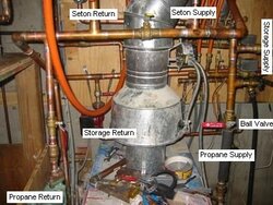
The Seton wood boiler is located physically further away from other components to minimize unwanted charging from storage - additional zone valves may be added to ensure no flow through the Seton when heating from storage.

The propane backup boiler is not shown because I am not sure how to work into the schematic. I want no flow through the propane boiler when heating with the Seton or from storage and I do not want the propane boiler to charge any storage. Not sure how to accomplish this - please help!!

A NFCS (NoFossil Control System) will be used to control all circulators and zone valves and to provide fail safe operation.

Please let me know any comments about how to maintain two temperatures of storage and how to incorporate the propane boiler (only for backup).

Thanks,
Steve
 

Attachments

  • System_09202008.gif
    System_09202008.gif
    35 KB · Views: 1,077
Very interesting approach, though I have my doubts about the NFCS ;-)

Couple of questions / observations:

1) The two leftmost coils in the storage are almost connected in parallel. Why not combine all that copper into one coil? Eliminate the zone valve to the left of the storage (we'll have a use for it in a minute).

2) I think that you have the same risk of the Seton circ drawing through the radiant zones that you have of the radiant circ drawing through the Seton. A zone valve just left of the radiant circ would fix this. I may have found one a minute ago ;-)

3) Seton input temperature protection?

4) How do you control / balance flow from the Seton bewteen the high temp and low temp loops? Maybe need a zone valve for each loop.....

5) If you can put the solar storage indirect physically lower than the other indirect, you could set them up to thermosiphon and keep the top tank hot.

6) DHW has a mixing valve for scald protection that's not shown?

7) Assuming that (4) is addressed, you could plumb the propane boiler with its own circ exactly parallel to the Seton. Both boiler circs would require check valves.

8) You might be able to use a larger diameter sidearm (to keep velocities low) adjacent to, but lower than your solar storage and main storage, so that thermosiphoning transfers heat to the storage if/when heat is available. That would give you two more zone valves for the flow control problem mentioned above.
 
I also have a concept plan to do a hybrid style system with pressurized and non-pressurized storage. This was to take advantage of the lower collection temps of the solar verses the higher temps of the wood boiler. I keep leaning away from it only because it is somewhat complicated. To me, until you add the propane boiler its hard to say how to control everything. The control scheme may be complicated. I will have to take the time to absorb your plan. I'd like to see it work though.

Mike
 
The two-temperature idea is part of the reason that my current 'perfect system' design has two 500 gallon propane tanks for storage. That would allow a choice of two different points for adding or withdrawing heat, and they'd likely be at different temperatures.

On of my frustrations is that I'll get a nicely stratified tank with a 40 degree drop. As soon as I start drawing heat from it, the return from my zones is hotter than the tank bottom and it destroys the stratification.

I use a stratification manifold for my solar coil, but the flow rates for the other loads and sources are much too high for that to work.
 
Thanks for the feedback...

Nofossil - responses to your comments

1) separate coils for directional charging and discharging of the storage tank, also allows simultaneous charging and zone heating. Zone valve is to limit EPDM tank to 150F

2) the design is basically a simplest unpressurized storage system based on your sticky. The main idea was that the load circ would work in series with the Seton circ when any zone required heating and the physically separated Seton would help to limit load circ flow through Seton.

3) Seton's don't need no stinking input protection :) - none required but I was going to put a Termovar in as soon as I get it from one of the members of Hearth...

4) Yes zone valve for each loop - lower loop has one (unless you take it). The idea was to always give the Seton a place to dump heat. Please enlighten me - for the storage tank to increase in temperature, doesn't the supply have to be at a higher temp (temp gradiant for heating and pressure gradiant for flow)? So, if the Seton does not go above 200F due to draft flap, then the upper loop will never go above 200F - correct? I will put a zone valve in upper loop...

5) Yes, thanks - I was planning on the solar indirect below the boiler indirect - and then build and isulation box around them both...

6) Yes, anti-scald AM101 (as some mastermind suggested :)). However, only one and not two like someone I know.

7) I use Grundfos with IFC because check valves are sometimes suspect. If the propane boiler was in parallel, then I would definitely need zone valves on both storage loops and to bypass the storage tanks in the upper loop.

8) Not sure I understand (big surprise), but would'nt the side arm require another circulator? Trying to minimize power and wood and eliminate propane. Power is the constraint - off grid and all.

Thanks again and I will try to post a revised schematic based on your comments.

Steve
 
SteveJ said:
Thanks for the feedback...

Nofossil - responses to your comments

1) separate coils for directional charging and discharging of the storage tank, also allows simultaneous charging and zone heating. Zone valve is to limit EPDM tank to 150F

As a thought experiment, try combining them. My theory is that you never charge and discharge at the same time. If you have a single coil (as in simplest sticky) and appropriate flow rates for both loads and the boiler, then there will be charging flow if the boiler is putting out more than the zones need, no flow if they match, and discharge flow if the zones need more than the boiler can provide.

4) Yes zone valve for each loop - lower loop has one (unless you take it). The idea was to always give the Seton a place to dump heat. Please enlighten me - for the storage tank to increase in temperature, doesn't the supply have to be at a higher temp (temp gradiant for heating and pressure gradiant for flow)? So, if the Seton does not go above 200F due to draft flap, then the upper loop will never go above 200F - correct? I will put a zone valve in upper loop...

You're right about the 200 degree maximum temperature, but that won't inhibit flow. You'll just get 200 degree return flow to the boiler. Your zone valve will cure that.
8) Not sure I understand (big surprise), but would'nt the side arm require another circulator? Trying to minimize power and wood and eliminate propane. Power is the constraint - off grid and all.

This is a brain spasm on my part, but I think I'm right. Imagine a heat exchanger (doesn't have to be a sidearm - plate would do) mounted just below the solar indirect tank. One side is connected to the top and bottom of the tank, and the other side is in the flow loop of the solar panel. If the solar panel water was hotter than the indirect tank, it would create thermosiphoning flow from the tank through the exchanger and back. If the solar water was cooler than the tank, no flow would happen,

You could do two of these - one for the indirect tank and one for the main storage tank. They'd need a bit of vertical height to encourage flow to start, but they would do what you want with no sensors or zone valves. Also, it removes the need for the lower tank to have an indirect coil - could just be any available tank.

I don't know if the thermosiphon flow would transfer as much energy as your panels generate, but it works just fine for me - up to about 100,000 BTU/day.
 
NoFossil,

I like the minimization of zone valves...

However, I am dealing with a 288 sq ft array of flat plate collectors in the Colorado sun - so I think the thermosiphoning may be too slow to remove enough heat. Also, the physical location (as shown in the schematic) limits the amount of thermosiphoning possible.

Extending on the flat plate collector idea, what about the schematic below?

The hot loop storage was eliminated due to 160 gallons at 200F for a hot tub and an indirect. I think the old storage tanks would have too much stand by losses to be of much benefit.

So, in the schematic below, the LP backup boiler is included and would not allow interaction with the storage tank by use of a three way zone valve.

Also, the schematic shows the components in relative altitude - the garage is above and to the side of the utility room where the DHW and backup boiler are located.

The Seton is in an unheated garage and the collectors are outside, so both loops would have propylene glycol. The rest of the system is contained in the heated space (with the exception of the submerged Amtrol heat exchangers in the storage tank in the garage). However, the location shares a wall with the heated space and freeze exposure should be minimal.

The Seton would run with very little controls necessary.

Any thoughts?
 

Attachments

  • System_09232008.gif
    System_09232008.gif
    39.2 KB · Views: 808
No time for detailed study today :-(

Nice. Some clever plumbing gymnastics.

You might want to show small-diameter lines for thermosiphoning for your indirects. I think a top-to-top and a bottom-to-bottom line would do it, plumbed with tees so that they don't act as a bypass when you're drawing water. These aren't strictly necessary, but without it you'll get temperature inversion in your indirects if you have a sunny day after a cloudy one. The basic idea is that if the top of the lower tank is hotter that the top of the upper tank, you want to provide a flow path from the top of the lower to the top of the upper and a return from the bottom of the upper to th bottom of the lower.

I'm thinking it might be worth adding a 3-way or at least a zone valve so that you don't have to preheat your return water to the FPHX by passing it through storage when you're heating with the Seton. Not really necessary, but my hunch is that it would improve performance a bit.

In both cases, you could just leave stubs to add these features if you don't have the time or inclination to do it now. I wish I'd left a bunch more stubs all over my system.
 
Thanks for the heads up on the thermosiphoning inversion...

Will the smaller pipes and tees prevent drawing from the wrong source?

The other issues with the design are:
1. water feed to the Seton loop - no pressurized feed to the garage.
2. water feed to the solar loop - usually just charged up and left.
3. rectangular storage - charging from ends with different sources - the stratification may end up having a large horizontal component.

Awaiting your solutions and comments :)

Steve
 
SteveJ said:
Thanks for the heads up on the thermosiphoning inversion...

Will the smaller pipes and tees prevent drawing from the wrong source?

The other issues with the design are:
1. water feed to the Seton loop - no pressurized feed to the garage.
2. water feed to the solar loop - usually just charged up and left.
3. rectangular storage - charging from ends with different sources - the stratification may end up having a large horizontal component.

Awaiting your solutions and comments :)

Steve

I hope somebody else chimes in on this one. I'm pontificating far beyond my actual experience here. Never stopped me before, though.

I have to confess that I don't have 100% confidence that you wouldn't get some bypass flow through the thermosiphon loop. The ideal solution would be to have separate tank ports. You might be able to use the drain port for the bottom, but there's only one top port on most indirects. You'd want to make sure that the 'normal' flow path has minimal restriction. A small amount of bypass flow won't hurt anything.

I actually shut off my pressurized feed to my boiler system. If there's a leak, I don't want to flood anything. I watch the pressure gauge and add a bit of water if needed - usually once or twice a year.

Any reason that you couldn't make your coils concentric or interleaved? Horizontal stratification will resolve itself by mixing.

For coils that are used for charging only, I'd consider placing them as close to the center as possible, and using only the bottom third of the tank. I might even get creative and install a stratifier manifold above the coil so that you get a column of rising water that can fan out horizontally when it reaches the right level. Some are made of fabric, others plastic. Think of a vertical pipe with large holes in the sides.

For discharge coils, a lot of surface area near the top is a good thing. I use a large rectangular grid in mine. Since my main coil is bidirectional, I also have a lrge rectangular grid near the bottom, though a coil and stratifier might have been a better choice.
 
Nofossil,

The new Ultrastor indirect has no drain - so the thermosiphoning would be teed off the main pathway.

I was thinking of doing cold to cold and hot to hot and the output of the solar charged to the input of the indirect (main path as in schematic) all with ball valves so I can manually control the thermosiphoning and can also select which source to use for DHW.

Since I am not smart enough to be as money efficient as you :), I would like to use items I already have for the charging and discharging.

I was thinking of the large piece of copper from an old flat plate collector for discharging the tank (first picture). about 4'x8' piece of solid copper with 1/2" fittings that could float at the top of the storage tank?

For charging, I have the HX coils from indirects as shown in the last picture. The long silver ones are State 60/80 gallon HX coils and the shorter ones are the Amtrol 40 gallon HX. All are copper. I am going to hang them from the deck boards across the top of the tank with 6AWG copper wire - so I can control where the coils are placed vertically. The silver coils are directional whereas the Amtrol coils seem like charging or discharging direction could be either way. I do have one in an Amtrol tank and the supply from the boiler is on the outside and returns on the inside of the coil. The tubes in the middle of the HX are temperature sensor wells. The silver coils seem to be at a good vertical height wheras the short coils seem that they should be hung lower. I was initially going to use the long coils for charging and the short for discharging but based on your suggestion for discharging as high as possible, I thought that the copper collector would work best - what do you think?

A Solvi stratifier could be placed inside the State HX but would probably not fit in the Amtrol HX. For reference the Amtrol HX is about 22" long and the tank is 46" deep.

The middle picture shows a fined HX from an old solar system - this was an external HX with four ports - I probably will not use but I thought I would show it to you for your review.

Let me know how you would assemble the pieces - please!!

Thanks,
Steve
 

Attachments

  • 3.JPG
    3.JPG
    15.7 KB · Views: 660
  • 2.JPG
    2.JPG
    24.1 KB · Views: 680
  • 1.JPG
    1.JPG
    23.5 KB · Views: 690
You are the king of heat exchangers!

All sounds good, but couple of questions:

What happens to those wood deck boards after they sit at 165 degrees and 100% humidity for a few months? Just asking - I really don't know. I think that people use similar environments to make wood soft and flexible enough to bend it into loops.

My thought for the Solvi style stratifier was a tube (maybe PVC) big enough to fit over the coil. This tube would have a ring of holes at the bottom to bring in the coldest water. The coil would be suspended just above these holes. There would be rings of holes every 6" or so all the way to the top, The coil would heat water which would rise until it found its level, where it would flow outwards through the nearest set of holes.

If this tube sat on the bottom, it could support the coil and reduce the risk of your decking boards becoming parabolas.

That giant copper plate would do a great job, but I'm not sure how the cooled water would flow down to the tank bottom during discharge, especially from above the plate. As I think about this, I wonder if a smaller finned coil like the ones on the right might not work well for discharge as well if fitted in a stratifier tube - just like the charging ones, but upside down.
 
Okay, I think that we have almost finished the plumbing design for our system that resides at my house :)...

The deck board idea came from http://www.builditsolar.com/Projects/SpaceHeating/SolarShed/Tank/Changes2007.htm. But on further review he uses them only around the side for passing the pipes - which I will probably do too - okay?

I am game for the Solvi - especially after review of the paper in the thread https://www.hearth.com/econtent/index.php/forums/viewthread/23489/.

The coiled HX are only 6 inches in diameter so would fit nicely in an eight or ten inch PVC Solvi as you suggest.

However, PVC is only rated to 140F http://www.harvel.com/pipepvc-sch40-80-derating.asp. Any alternatives come to mind?

If the PVC sat on the bottom, would it rub and possibly compromise the EPDM?

The CPVC setup used by WoodNotOil http://woodnotoil.googlepages.com/constructionlog is intriguing. What about a solvi built from an EPDM wrapper around a CPVC frame with slots every 6 inches?

The storage tank water storage dimensions are 92" L x 34-1/2" W x 46" D. So, given the physical limitations, what is the best placement for the charging and discharging Solvis?

If the copper plate is used for discharging, it could be placed at a 45 degree angle for cold water shedding. However, the copper plate would take most of the tank volume away from the Solvi - copper plate dimensions are - 74" L x 33" W x 1/2" D.

One way I see to use the copper plate is diagonal when viewed from the top with discharge cold port on bottom and hot port on top withthe coiled Solvi chargers completing the percent sign - from top looks like % - rough drawing below.

Suggestions? Others using Solvi style stratifiers?
 

Attachments

  • SolviStorageTank_09282008.gif
    SolviStorageTank_09282008.gif
    15.9 KB · Views: 616
That all looks good. I don't know what happens to PVC at 160 degrees. I suspect it loses strength and won't meet its pressure spec - no problem in this application. You could make pads out of a few extra pieces of EPDM beneath any objects touching the bottom or sides.

This is all learning at this point. I started out on my journey knowing none of this. Hopefully if we share, others who follow will have an easier path.
 
The question I have at this point is if it is worth using the copper plate or just use Solvi for charge and inverted for discharge???

The copper plate is from a solar collector designed for low flow - so not sure how this will work charging or discharging...

I guess I could use it for charging the tank from the solar collectors?

What is your professional opinion?
 
SteveJ said:
The question I have at this point is if it is worth using the copper plate or just use Solvi for charge and inverted for discharge???

The copper plate is from a solar collector designed for low flow - so not sure how this will work charging or discharging...

I guess I could use it for charging the tank from the solar collectors?

What is your professional opinion?

I don't have a professional opinion - this isn't my profession.

I'm intrigued by the whole Solvi concept, and I'm thinking that may be as good as it gets for both charging and discharging.. The only difference that I'd suggest from what you've drawn is to have a large cross-section inlet at the bottom for a charging tube - perhaps just suspend it 2" above the bottom on legs or blocks - so that it draws in only the coldest water. No holes in the lower section where the coil is, but then holes all the way to the top (which should protrude just above the surface to ensure that upward momentum does not encourage water to continue up through the top rather than making a 90 degree turn and going out through the sides.

Discharge could be the exact same idea, upside down.

The problem with the plate is that any installation configuration has at least some potential stratification issues. Your diagonal orientation is interesting, and using it for solar is as good an idea as any. You could configure the solar circ to run only when solar output is higher than tank top temp, and you'd be fine.
 
Nofossil,

Sorry about the "professional opinion" question - I, like others whose systems you have helped designed, am so amazed to find out that you are not a professional :)

I like the suspending of the charging Solvi above the tank bottom and extending above the water level top with the coil in the bottom of the Solvi with no holes around coiled finned portion. Seems like it should force maximum stratification...

For discharging, I was going to use the shorter coils pictured with the top of the Solvi a couple of inches below the water level top and the bottom resting on the tank bottom. Again, no holes in the Solvi until after the coiled portion of the HX and the HX at the top of the Solvi. However, this seems to put a possibly unrealistic concern about water level to make sure it is always above the discharging Solvi top. Any brilliant insights here?

How about the Solvi tube diameter? The coils are 6" in diameter and the tank is 34-1/2" wide. Would an 8" or 10" diameter Solvi be more appropriate? Seems like the Solvi should concentrate on vertical flow with minimal stratification disturbance. So, would a wider tube be better to minimize thermal flow velocity?

Thanks again for playing along.

As soon as the system is functional, I will send data for your habit.
 
Okay - got the single unpressurized system plumbed with the three sources (Seton wood boiler, unpressurized storage, propane backup boiler) in parallel as shown in picture below.

Question

The propane boiler has a spring flow check (that works!), but when the ball valve indicated is opened, the propane boiler heats up to about 140F when the Seton is the only heat source on and the indirect water heater is the only zone open and the Grundfos 15-58 is on low speed.

So, how can the propane boiler be heated by the Seton if there is no flow through the propane boiler???

I can put another flow check near the ball valve but I do not understand why the propane boiler is heating up when there is no flow through it - and losing heat through the chimney.

Suggestions for stopping flow through the propane boiler?

Thanks,
Steve
 

Attachments

  • System_10102008_small_annotated.JPG
    System_10102008_small_annotated.JPG
    32.7 KB · Views: 314
I have been reading this discussion with much interest with regards to the heat storage. Maybe this link will help you out somewhat ( or confuse you more :) )
http://www.iea-shc.org/publications/downloads/task32-d2.pdf

I am wondering if the stratifier you are planning are going to do much for you. The impressing I get of these things is that fluid needs to flow within these for them to work. Also the Solvis type needs to have one-way flaps installed to function or you will get "phantom flow" or thermal syphoning whitin the stratifier, especially when the diameter gets larger. In the article on stratification they tested the fabric stratifier to eliminate the need for valves, but they do need some flow within.

Henk.
 
SteveJ said:
Okay - got the single unpressurized system plumbed with the three sources (Seton wood boiler, unpressurized storage, propane backup boiler) in parallel as shown in picture below.

Question

The propane boiler has a spring flow check (that works!), but when the ball valve indicated is opened, the propane boiler heats up to about 140F when the Seton is the only heat source on and the indirect water heater is the only zone open and the Grundfos 15-58 is on low speed.

So, how can the propane boiler be heated by the Seton if there is no flow through the propane boiler???

I can put another flow check near the ball valve but I do not understand why the propane boiler is heating up when there is no flow through it - and losing heat through the chimney.

Suggestions for stopping flow through the propane boiler?

Thanks,
Steve

Is it possible that there's a thermisiphon loop? These things can be subtle and pesky.
 
Henk,

Thanks for the reference to the paper. You got me rethinking the whole tank exchanger layout - with heat exchangers and no flow in the tank, it seems that the external stratifiers may not do much. the only flow will be due to the tank water density changing as a result of being heated or cooled from the submerged exchangers.

I am thinking about mounting the charging (putting heat into the tank - no fluid flow in the tank) heat exchanger coils horizontally in the tank about 2/3 up and the letting the heated tank water seek stratification.

For discharging (removing heat from the tank - again no fluid flow in the tank), I thought that the large copper plate would be placed across the top - cool water would flow through several feet of Pex half way up the tank - again to seek its own heat level.

The alternative plan is to take a few Home Depot buckets and drill holes in the side and encase the heat exchangers vertically.

Opinions?


Nofossil,

Thanks for the thermosiphoning hint - it appears that the external spring flow check is not working as described - big surprise!!

If the ball valve on the propane return line is closed then there is no raise in the propane boiler temperature when off.

So, I guess I will either try a Grundfos with and IFC or place a zone valve in the propane boiler loop or get rid of the propane boiler altogether.


Thanks,
Steve
 
Hi Steve,

I don't have all my plans firmed up yet either. I know I will have a charging coil, but it will be almost on the bottom. I think a stratifier may work above a coil but needs to "catch" the rising water that was heated in maybe a inverted funnel like contraption leading into the stratifier.
This article (posted earlier) helped me a lot too, my main conclusion from it was that I need a taller tank to capitalize on max stratification. http://www.preheat.org/fileadmin/pr...bo_Heat_storage_for_solar_heating_systems.pdf

By putting your charging coil just under the top 3rd ( as I understand in 2/3 up) you will get the hot water in the top of the tank, but your charging efficiency will get lower when the hot water gets to the coil level (from the top down) and reduces you delta T. You could do this with coils at different levels and when this happens switch to a coil lower down in the tank.
At one time I was considering a large charge coil from 1/2 " pex ( 4 paralell tubes) in the bottom of the tank. With the tank at 6 ft tall, I may rethink this and put the coils in a stratifier or more then one and split the parralell coils in aech ther own, like on page 17 of the link above, left bottom of the page.

On the discharge end I am looking at a DHW copper coil in the top of the tank, and for the floor heat using the storage water from the top and re- entry through the stratifiers that charge the tank. The key here in my mind is the velocity of the water entering the stratifiers.
I hope this didn't confuse you or me any more, but it is sometimes good to sound it of and get some thoughts on the plan before actually putting the tools to it...

Henk.
 
Henk,

Thanks for the links - still trying to digest the material...

Would it be possible for you to post a drawing of your tank?

What material are you going to use to make your stratifiers and hold them in place?

As I understand your description, you are going to use the water in the storage tank for space heating - correct?

Is your tank pressurized or unpressurized?


My storage is an EPDM rectangular box - only 4ft high for structural integrity. The storage tank is made and I feel safer without the pressurized propane tanks (and I am out of money :long:). All of the water in my tank is stationary - like nofossil's - with all heat transfer done by submerged heat exchangers.

I was thinking of doing either vertical plates our of epdm or inverted funnels out of epdm. However, since my tank is longer than high, I may lay the heat exchangers (pictures on previous page) on the bottom and float the copper plate on top for discharge.

Thanks for the delta T reminder - I do want coldest possible back to heat sources (wood boiler and solar panels).

I was thinking that on each end of the storage box that I would have an epdm curtain behind which would be the pipes into and out of the heat exchangers. Hopefully, to minimize disruption to stratification.


Home Depot bucket elaboration:
Similar to p.17 upper right corner http://www.preheat.org/fileadmin/preheat/documents/intersolar/Simon_Furbo_Heat_storage_for_solar_heating_systems.pdf
Bottoms cut out of buckets for main funnel and space between buckets to allow water out.
Charge with bucket tops down
Discharge with bucket tops up.
Modification to picture would be to use spacing described by nofossil - large space on bottom for charging coil and large space on top for discharging coil.

For my rectangular box storage - I was thinking of running the funnels along the diagonals of the solid - from bottom front corner to top back corner.

Please keep posting and I will try to find some references and contribute more.

Steve
 
Status
Not open for further replies.