Using the taco, "selecting circulator pdf" i have some ?s

  • Active since 1995, Hearth.com is THE place on the internet for free information and advice about wood stoves, pellet stoves and other energy saving equipment.

    We strive to provide opinions, articles, discussions and history related to Hearth Products and in a more general sense, energy issues.

    We promote the EFFICIENT, RESPONSIBLE, CLEAN and SAFE use of all fuels, whether renewable or fossil.
Status
Not open for further replies.

atvalaska

Member
Jul 22, 2014
116
nenana
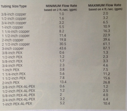
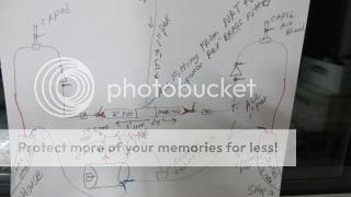
Here is what I have and where I'm at ,a outdoor boiler 75' away from the house , I did step 1 and my target flow rate it comes to 2.50 gpm (30%glycol/24000 btuph) ...on to step 2 , tube size ,I got that covered as I buried 1.25 pex (really it more like 1 1/2 as my uponor fittings of 1.25 "fell in the pex" so much so I had to use uponors 1.50 inch EP fittings) >> SO MY question is do I just figure out the piping using just the pipes and fittings "getting it to the house and back" ? This would be step 3 ,sounds easy enough, then Step 4 says to do a head loss calc for each "parallel loop"( p-loop is that each zone in atvalaska speech?is that what they mean?) SO I will/can easily come up with a number for the house to boiler shed , then I need to do each separate "zone?"/or is it a parallel loop? inside the house. and starting from where.....am I reading to much into this ? i need to call somebody !!!! :(
 
20 views and nobody can lead...?


I think your gpm number is off, 2.5 gpm at a 20°∆T that would be 2500btu/hr. Maybe you mean 25 gpm, which would require 1-1/2" tube to move?

After that the head calc is all the piping and fittings the pump circulates through.

With a radiant manifold with multiple loops, for example, just the pressure drop (head) of the longest loop, not the total. Total of the loops for gpm, however. Six loops of 1/2 gpm would be 3 gpm.

Sometimes drawing it out on paper helps see the piping circuit.
 
His flow rate is "right" if he REALLY only needs 24k btu. 1k btu/ 1 gpm is the general rule.

From there it is plug and play into the next formula.

k for 1.5" pex: 0.00036
c for 30% glycol: 1.088
f^1.75: 4.970
L = ~150 (75 each way, you need to figure out the fittings)

Hl = VIRTUALLY NOTHING

Your pex is WAY bigger than it should be to move 24k btu. Are you SURE you only want to move 24k btu?

ac
 
20 views and nobody can lead...?
Sorry, can't really visualize what your layout is. Sounds like there will be one calculation for the pump that feeds the heat exchanger and another calculation for the pump that pulls through a mixing valve and feeds the PEX. People are reluctant to invest time figuring out what you need based on guesswork only to find out later it was a waste of time because important information was left out. Can you provide a schematic?

(Agree with avc that 24000 btu / hour sounds quite low for max capacity. My fairly small load averages about 25000 btu / hour for the whole heating season and can require more than twice that when the temperature is in the single digits either side of zero and the wind starts howling.)

(Bob made a rare-for-him arithmetic error when he came up with the 2500 btu / hour number. Your 2.5 gpm/24000 btu calculation sounds right for glycol.)
 
Last edited:
I did oversize the pipe from boiler to house (shop to)..the idea was> it would use a small and thrifty pump to keep the water moving 24/7 ..I have the shop on a gf alpha and it burns 14 watts / 5 gal I have to watch my power use .... I will use some solar/wind as back up juice ...power goes out all the time here..its 9 miles to the next guy "on the line" ...THEM are the really numbers its 23,337 something I bumped it to 24,000 to make it easy https://www.hearth.com/talk/threads...t-lost-numbers-done-help-me-read-them.139017/
 
Last edited:
I do not think I will need a heat exchanger , i'm going to run the water into the house and thru 3 Uponor EP manfolds and back .. what I guess I'm trying to figure is if I can get away with 1 taco 4way 1" valve that flows 8.4 cv , I have warm board and no fittings in any on my pex it just hooks to the manifold ,then it runs its loop than back to the return manifold. ( between the manifold and where the pex pop's up thru and runs the floor, is all sealed in 2" spray foam)
 
Sorry, can't really visualize what your layout is. Sounds like there will be one calculation for the pump that feeds the heat exchanger and another calculation for the pump that pulls through a mixing valve and feeds the PEX. People are reluctant to invest time figuring out what you need based on guesswork only to find out later it was a waste of time because important information was left out. Can you provide a schematic?

(Agree with avc that 24000 btu / hour sounds quite low for max capacity. My fairly small load averages about 25000 btu / hour for the whole heating season and can require more than twice that when the temperature is in the single digits either side of zero and the wind starts howling.)

(Bob made a rare-for-him arithmetic error when he came up with the 2500 btu / hour number. Your 2.5 gpm/24000 btu calculation sounds right for glycol.)


My mistake, thanks for catching that EW.

I'm confused why a boiler would only be supplying 2.5 gallons thru a 1-1/4" pipe. Perhaps other loads are connected to the loop, or boiler?
 
24,000 ..my bad..... I plan to heat my D-hot water then off to a mixing valve or two , into 3 manifolds...looping the floors back into the return line to the boiler.
 
I'm saying you need two pumps, one to supply your DHW HX, and another that will pull through a mixing valve (possibly with outdoor reset) and will then feed your in-floor loops.

Step 1 for the 24000 btu per hour in-floor loads: DeltaT entering the mixing device and returning to the boiler through the boiler-to-house loop will be something like 70 degF (180 degF supply minus 110 degF return) give or take, so gpm on the boiler-to-house loop will be 24000 / (70 * 500) according to Formula 1 on the Taco worksheet. This works out to 0.68 gpm, which I would suppose is the smallest boiler-to-house gpm in the history of hydronics.

With 0.68 gpm to feed the in-floor loads the pressure drop in the boiler-to-house loop will be something like 0.059 feet of H2O, not counting the fittings and valves. Negligible.

Since the boiler-to-house loop is hardly a factor, all you need is a pump big enough to feed your in-floor loops; the same pump that feeds the in-floor loops can pump all the way from the boiler, through the in-floor loops, and all the way back to the boiler. After you figure out the gpm you need for each loop (0.75?), figure out what the head loss is for any given loop. Then pick your favorite constant pressure ECM pump: B&G Vario, Wilo Stratos, or Grundfos Alpha, and look at the pump curve and how many gpm it can supply at the head loss number you came up with. For instance if you picked 0.75 gpm for each loop, the the head loss would be about 6.5 feet and any of the pumps mentioned would supply in excess or 10 gpm at 6.5 feet of head, which is 13 loops at 0.75 gpm each, not counting the mixing valve, fittings, valves, and the boiler-to-house loop.

For DHW just need some tiny pump that pulls all the way from the boiler independently of what the house loads are doing.
 
Last edited:
I hope this helps for moving the energy from the boiler to the house:

Q of 24kbtu with 20F deltaT requires 2.4 gpm
You said 1 1/4" pex which I have as 1.054" ID (don't understand the 1 1/2" ID if it's 1 1/4")
IF 1.054" ID the velocity is only .9 fps (very low, but very nice)
Assuming 10 elbows, 12 tees, 4 ball valves and 100' boiler to house (200' round trip) = ~7.5' head loss

This is just plug and chug from the TD10. Leaving work now. Any wrong assumptions I'll be glad to fix tomorrow. EW has a model also. Wish our home needed 24k/hr... maybe in April or May.

You need to add a big extension on your house to take advantage of that supply line. I'm thinking your 24kbtu estimate is low. Cheers


But keep an eye on flow rates that get too low, it's hard to push air out in front of a fluid stream below 2 fps. You might consider turning turn the pex into a loop as a primary circuit, and pull the lower flow rate from that.

One pump circulates then loop at 2- 4fps, the additional circs flow the loads at the required gpm.
 

Attachments

  • Gpm: Fps chart.png
    Gpm: Fps chart.png
    45.2 KB · Views: 192
1" uponor pex for every thing after it leaves the thermo pex 54724091_484931_full.jpg top halfs like this lower half
IMG_01582.jpg
here is the lower half of my 4 way set up in the shop here is a link to what it looked like as I started this heat chit !
 
Last edited:
But keep an eye on flow rates that get too low, it's hard to push air out in front of a fluid stream below 2 fps. You might consider turning turn the pex into a loop as a primary circuit, and pull the lower flow rate from that.

One pump circulates then loop at 2- 4fps, the additional circs flow the loads at the required gpm.
A minimum of 2 fps is necessary for purging the line, but from that point on there would be no mechanism for gas to come out of solution and accumulate in the boiler-to-house loop.
 
Last edited:
IMG_0161.JPG IMG_0161.JPG here is what the back wall of my boiler set up looks like... in the" middle bottom" I added the "insert" of the side view of the boiler ..follow the * at the top cente...oh oooo /looks like it got cut off in the pic (its on top of that "5' of pex" ..that's in the back center"... the 3rd pic in this set is the "right hand side of my drawing" most of the thermo pex coming thru the floor is blocked from view by that blue "coolant boiler over barrel" !....
 

Attachments

  • IMG_0062.JPG
    IMG_0062.JPG
    191.5 KB · Views: 114
  • IMG_0063.JPG
    IMG_0063.JPG
    154.1 KB · Views: 104
Last edited:
IMG_0761.JPG in this view u can see my boiler shed with the house behind ...( to get the lay out) 1/2 story (but full sized) on top of 2 full stories... the stairwell is in that "jut out"..
 
Last edited:
But keep an eye on flow rates that get too low, it's hard to push air out in front of a fluid stream below 2 fps. You might consider turning turn the pex into a loop as a primary circuit, and pull the lower flow rate from that.
One pump circulates then loop at 2- 4fps, the additional circs flow the loads at the required gpm.

Copy Bob/EW. Explains the low end of Taco's recommended 2-4 fps. I googled 1 1/2" pex to get an ID and gave up.

Nice home ATV. Bet you have a great view.
 
Status
Not open for further replies.