Circulator pump for Water / Air Heat Exchanger

  • Active since 1995, Hearth.com is THE place on the internet for free information and advice about wood stoves, pellet stoves and other energy saving equipment.

    We strive to provide opinions, articles, discussions and history related to Hearth Products and in a more general sense, energy issues.

    We promote the EFFICIENT, RESPONSIBLE, CLEAN and SAFE use of all fuels, whether renewable or fossil.
Status
Not open for further replies.

hartkem

Member
Jan 24, 2012
249
KC
Im slowing making progress on my eko 40 install. I have the boiler plumbed in outside to my thermopex and the thermopex through the basement wall plumbed to my 500 gallon pressurized storage tank. I now need to run lines from the storage tank to the heat exchanger in my forced air duct work. The duct work is only about 7 feet away from the storage tank. I will be installing a brazetec 18 X 18 exchanger in the plenum. I would like to get up to or exceed 100,000 btu so I would need to move 10 gpm or more. I can figure the head loss for the 1" copper running to the exchanger but can't find info for the head loss through the heat exchanger. I was think of a taco 005 or 007 with IFC. Any thoughts

Thanks in advance
Mike
 
Doesn't seem like a WAHX would make much resistance, nonetheless my thinking would be to use a 'high head' steep curve pump like a 15-58 or 008 that would provide more than enough flow at low resistance and would still provide the 10 gpm if the resistance is more than you expect.

Also, since you are running storage remote from the boiler it would be important to minimize return temperature to storage. As always, I suggest either a thermostatic diverting valve as suggested by the Tarm reference designs, or a small hydraulic separator/buffer tank between the return from the WAHX and storage. Honeywell Braukmann has adjustable diverting valves with a Cv of 5.8 that look like they would be appropriate.
 
Also, since you are running storage remote from the boiler it would be important to minimize return temperature to storage. As always, I suggest either a thermostatic diverting valve as suggested by the Tarm reference designs, or a small hydraulic separator/buffer tank between the return from the WAHX and storage. Honeywell Braukmann has adjustable diverting valves with a Cv of 5.8 that look like they would be appropriate.

Eliot,

Could you explain the logic behind why the diverting valve is needed. Also, would a manually adjusted one like this do the job?
 

Attachments

  • 20001-2.jpg
    20001-2.jpg
    2.3 KB · Views: 215
Could you explain the logic behind why the diverting valve is needed. Also, would a manually adjusted one like this do the job?
With high temperature loads like baseboard and WAHX in a system with wood boiler and storage you have two conflicting design goals. One goal is to have minimum return temperature to storage in order to maximize heat storage capacity, and the other conflicting goal is to have good old fashioned hot heat to get the job done. Your situation is aggravated by the remote storage because it will be impossible to transmit the full output of the boiler to storage over the distance required unless the return temperature from storage is low enough to establish sufficient deltaT. (Best would be to have in-floor radiant and/or low temperature panel radiators, but many of us can't pull that off in our short time here on Earth.)

Getting the flows and temperatures just right to strike a good balance is difficult, so having adjustability built into the design gives you the ability to tune for acceptable performance. One method is to use a diverting valve that sends some flow back around through the WAHX such that the temperature returning to storage is maintained below the setpoint of the diverting valve. You can adjust the return temperature lower and lower until you decide the fan is running too much and the air is not hot enough, and then go back the other way until you're happy.

The adjustable diverting valves are nice, but they tend to have a low Cv, so need to plot the flow curve against your pump curve and see if you can get the btus per hour you need assuming a realistic deltaT. The Honeywell I mentioned earlier can be used as a diverting valve, and has a fairly high Cv of 5.8 compared to a more typical 3.5 to 4.0 for this type of affordable valve, but I couldn't find the adjustability range. I'm having no trouble delivering 75000 btu per hour through a Taco 5000 that has a Cv of 3.8, but that's just not quite as much peak heat flow as most systems require. Both the Honeywell and the Taco are the same type of manually adjustable valve as the the one pictured above, but beware that not all mixing valves are approved by the manufacturer for diverting valve applications.

Another option would be to look into a configuration that could take advantage of a Tekmar control with a variable speed pump and outdoor reset, which could do an excellent job of minimizing return temperature, but that's quite a bit more money and it might be hard to find someone competent to set the whole thing up affordably.
 
Eliot,

The honeywell valve in questions states that it is manually adjustable and doesn't have any type of automatic mixing. Therefore if I have it manually set it to deliver say 160F water to the WAHX when my storage temp is 180F it works as intended but what seems to me would be a problem is when my storage temp drops to say 140 and the mixing valve is still sending some of that water back through the WAHX, now I have less than 140F since some of the return water dilutes this 140F water and lowers the temperature making my WAHX useless. Just trying to get this all straight in my head. Also the CV rating of the valves concerns me. If I understand correctly if I push 5.8GPM though a valve with 5.8CV I would have about 2.3 ft of head loss. If I push 12 GPM through it I would have roughly 4.6ft head from the valve.

check out the Taco I-series outdoor reset mixing valves. they're really slick for air coils, as you can tweak them all you want, and get the return water temp pretty low. 100kbtu seems a lot for an 18x18 air coil. usually I see air coils designed for a 30 deg delta T. that's 6.6 gpm which you can get thru the 1" Imixing valve.

I assume you won't need 100,000btu all the time, just on design days? consider putting 2 coils in series in the duct if it won't cause problems with the blower, you'll get a higher delta T and be able to use lower water temps for the same output to the air. the additional $200 for that small coil would be money well spent. especially with 500 gal storage you'll increase your heat storage due to the higher delta t in the storage tank.

just my $.03

Karl
 
  • Like
Reactions: ewdudley
The honeywell valve in questions states that it is manually adjustable and doesn't have any type of automatic mixing. Therefore if I have it manually set it to deliver say 160F water to the WAHX when my storage temp is 180F it works as intended but what seems to me would be a problem is when my storage temp drops to say 140 and the mixing valve is still sending some of that water back through the WAHX, now I have less than 140F since some of the return water dilutes this 140F water and lowers the temperature making my WAHX useless. Just trying to get this all straight in my head.
I was suggesting that the a mixing valve be installed in a diverting configuration. Flow leaving the WAHX would enter the 'mix' port of the valve and it would leave by the 'hot' and/or 'cold' ports. A diverting valve will balance such that water leaving the 'hot' port is no hotter than the valve setpoint. The 'hot' port (cold, actually) connects to bottom of storage and the 'cold' port (hot, actually) tees back into the line going to the WAHX somewhere upstream of the pump. This way you can guarantee that water returning to storage is below some maximum temperature.

Actually with a single relatively stable load you could accomplish pretty much the same thing with a mixing valve like Karl is saying. The diverting valve technique is just more specific to controlling maximum return temperature automatically despite changes in temperatures and flows.

Also the CV rating of the valves concerns me. If I understand correctly if I push 5.8GPM though a valve with 5.8CV I would have about 2.3 ft of head loss. If I push 12 GPM through it I would have roughly 4.6ft head from the valve.

head_loss_in_feet_of_H2O = (1.52 * gpm / Cv)^2
= (1.52 * 12.0 / 5.8)^2
= 9.89 ft H2O

But like Karl is saying, hopefully your coil is big enough to give you 30 degF deltaT or more, so your required flows could be more like 6 or 7 gpm. You're right, the Cv's for these types of valves is small, but if they're big enough for what you need to do then you're golden. Maybe you can fire up the existing system and use an IR gun or contact thermometers to see what kind of deltaT you're getting today, and then estimate what the flow is based on the pump and pipe you have, it would give a nice sanity check.
 
Eliot,

I'm finally starting to understand what your saying. Sorry but I'm an auto mechanic, not a hydronics master. So far I know that its important to recirculate the WAHX water to keep return temps to storage low. I assume this keeps the top of the tank hot and bottom cold. Im trying to understand why keeping the tank stratified is so important. Also, is deltaT, change in temp? I hope im not upsetting anyone by asking so many questions but some of the words used go over my head. I have a new found respect for the complexity of heating with water.
 
And to clear one more thing up. Is the answer to this question true. I found this on pex supply. I thought this was called thermostatic because it adjusted temperature based on your setting.

Honeywell Braukmann 1" 3-Way Mixing Valve (Female Sweat Union)
Q:
Does this valve actually sense the temperature and adjust for variances or just mix the hot and cold? I need a constant 120 degree supply to my floors.
Thanks.
Asked on 10/1/2010 by Anonymous
Know the answer? Answer this question
1 answer
CUSTOMER CARE
A:
The valve does not sense the temperature coming into the line, it simply mixes the hot and cold lines together to reduce the water temperature. There is a valve on the mixing valve that you manually adjust to change the temperature. Normally it is recommended to have a temperature gauge in line so that you can adjust it accurately to the temperature you need.Answered on 10/5/2010 by PexSupply Staff from N
 
I'm an auto mechanic, not a hydronics master. So far I know that its important to recirculate the WAHX water to keep return temps to storage low. I assume this keeps the top of the tank hot and bottom cold. Im trying to understand why keeping the tank stratified is so important.Also, is deltaT, change in temp?
Yes indeed, deltaT is change in temp, and gpm is flow. Taken together deltaT and gpm is about all there is to hydronics.

DeltaT is voltage, gpm is amperage, and pipe and components are the wires and resistors.

The amount of power transmitted though a pipe is gpm times deltaT: btu_per_hour = gpm * deltaT * 500. Same as watts is amperes times change in voltage: W = A * V. Watts, horsepower, and btu per hour are all units of power, work done per unit of time.

Just as you can only get about so many amperes to flow through a wire, you can only get about so many gpm to flow through a pipe or component. The amount of flow we can get through a pipe is limited by how fast the water flows and by how big of a pump we can afford to run, and when we're all said and done there's a certain fixed maximum gpm that will flow through a particular circuit when it is put into service.

So if the gpm is fixed and constant according to the circuit design, then power can only vary according to deltaT. More deltaT, more power, same as more voltage more horsepower. With only 12 volts to work with it takes a wire as big as your little finger to run a five horsepower starter motor, but if you could use 220 volts it could be done with 12 gauge wire. 5 hp is about 3700 watts, which is about 12500 btu per hour.

So one reason tank stratification is important is that stratification determines how cool the water is that goes to the boiler, which determines how much deltaT the boiler has to work with, which determines how much boiler power can be transmitted to storage. If the piping from storage to boiler flows about 10 gpm, and the boiler wants to put out 100000 btu per hour, then deltaT has to be at least 20 degF (100000 btu per hour divided by 500 times 10 gpm). Likewise if the boiler to storage circuit only flows 5 gpm, then you need 40 degF deltaT to transmit 100000 btu per hour.

And a bigger reason stratification is important is that it determines how much heat the storage can store. If you can cool storage down from 180 degF to 140 degF then you have extracted twice as much energy as pulling down from 180 degF to 160 degF. The size of your WAHX will determine how cool you can get away with when you try to lower your return temperature.

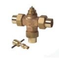
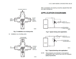
A thermostatic mixing valve or diverting valve does sense the temperature. An automotive thermostat is a fixed setpoint diverting valve. A 185 degF thermostat will divert coolant back to the engine until block temperature gets above 185 degF, then it starts sending some flow to the radiator. When it gets hot enough all the flow will go to the radiator. A mixing valve configured as a diverting valve is the same idea, with an adjustable setpoint. In fact that the fixed setpoint thermostatic diverting (mixing) valves available from Termovar and Danfoss have what appears to be a plain old automotive thermostat inside.

Flowing the other direction they become mixing valves and they will sense temperature and adjust the amount of hot port flow and cold port flow to mix them together to deliver water at the setpoint temperature. I can't make much sense out of the PexSupply answer, but the idea should be that if the valve setpoint is 120 degF, and there is water 120 degF or hotter available at the hot port, and there is water 120 degF or cooler available on the cool port, then the valve should be able to deliver water that is more or less a constant 120 degF out the mix port.
 
One could also at installation maybe plumb in some stubs on the return line that additional loads could easily be plumbed into if you find your delta T not large enough when bringing things on line. I think I will do that so that I could hook up a couple of cast iron rads in my basement or runs of slant fin if it would make things work better. The heat in the basement wouldn't go to waste. From my experience with life in general, sometimes no matter how many times the numbers are crunched ahead of time, things don't always end up working as they should have - so I try to anticipate how to fix or adjust more easily ahead of time. Doesn't always work out though...
 
Received my valve today. I think I need the V100R accessory to make this valve automatically adjust.
Also, does it matter where my circulator pump is located in relation to the diverting valve? I was going to install it before the diverting valve because I have more room in that location.


The Honeywell Braukmann V135 valve is designed for
hydronic heating systems and can be applied as a mixing
valve or a diverting valve. The V135 is normally used with the
T100R series thermostatic control, which is equipped with a
strap-on pipe sensor for attaching to the heating system pipe
by means of a clamp. A plastic handle is also provided with
the V135 for manual operation of the valve
 
Inspected the valve today and unscrewed the plastic knob on top and it indeed is not thermostatically adjustable without the V100r accessory. The accessory appears to be a thermocouple type device that pushes down on the pintle of the valve. I
One could also at installation maybe plumb in some stubs on the return line that additional loads could easily be plumbed into if you find your delta T not large enough when bringing things on line. I think I will do that so that I could hook up a couple of cast iron rads in my basement or runs of slant fin if it would make things work better. The heat in the basement wouldn't go to waste

This comment got me thinking. I really wanted to install in floor radiant but since I have a finished basement that is completely drywall except for my utility room I had to look at other options. I realized the other day that I can look down the ceiling joists between the drywall and subfloor into the finished area. Wondering if I could slide a loop of tubing down each bay to heat the upstairs. This area would be directly below the main living area. My house is a 1 1/2 story that isn't sprawling. I wouldn't be able to secure it in any way and maybe I could tee a manifold off the return line of my heat exchanger to really lower the temps. Just a thought. Opinions?
 
Inspected the valve today and unscrewed the plastic knob on top and it indeed is not thermostatically adjustable without the V100r accessory. The accessory appears to be a thermocouple type device that pushes down on the pintle of the valve. I


This comment got me thinking. I really wanted to install in floor radiant but since I have a finished basement that is completely drywall except for my utility room I had to look at other options. I realized the other day that I can look down the ceiling joists between the drywall and subfloor into the finished area. Wondering if I could slide a loop of tubing down each bay to heat the upstairs. This area would be directly below the main living area. My house is a 1 1/2 story that isn't sprawling. I wouldn't be able to secure it in any way and maybe I could tee a manifold off the return line of my heat exchanger to really lower the temps. Just a thought. Opinions?


You would need to fasten the tube in the joist bay somehow. If not fastened it will move as it is heated and cooled and cause quite a racket. It would be hard to control the heat transfer also. Depending on the floor coverings above (R-value) most of the heat energy would possibly transfer down. You would also need to insulate the end of every joist bay to prevent the energy from going out the rim joist area.

There are some low profile "over the top" radiant products available for retro fit. Working from the top would be a better option. Viega and Uponor offer the dry systems for retro work.

Panel radiators are a great method also. They provide radiant and convective heat transfer. Equipped with a thermostatic radiator valve, every room has temperature control.

hr
 
There would be no way to fasten the tubing in the bays. After looking closer there is to much stuff in the way to make it worth while anyway. I will stick to the WAHX. I just need clarification on the pump location when using the diverting valve. Diagram with the valve shows the pump between the diverting valve and WAHX on the supply side. I would like to locate it on the supply side before the diverting valve due to available room.
 
There would be no way to fasten the tubing in the bays. After looking closer there is to much stuff in the way to make it worth while anyway. I will stick to the WAHX. I just need clarification on the pump location when using the diverting valve. Diagram with the valve shows the pump between the diverting valve and WAHX on the supply side. I would like to locate it on the supply side before the diverting valve due to available room.


Generally the pump is downstream or pulling flow thru the mixing device
 
Generally the pump is downstream or pulling flow thru the mixing device


Here is what Honeywell suggests. Are you asking about putting the pump at the "AB" port flowing into the valve?
 

Attachments

  • Screen shot 2012-07-09 at 6.54.55 PM.png
    Screen shot 2012-07-09 at 6.54.55 PM.png
    29.9 KB · Views: 417
No, I was asking about putting it between my storage tank and the diverting valve but realized it probably wouldn't recirculate properly so I found the room to install it the way the honeywell diagrams shows.

Today I received my 18 x18 coil from brazetek and after some trial and error decided I could order another coil so I can install them in an A coil configuration. Hopefully I can uses really low temp water doing this. I think I am going to plumb the two coils in parallel using a homemade manifold to connect the ports together.
 
Hartkem, Time to get the camera out and show us some pics.
 
IMG_1477.JPG As promised is a few pictures. I included a pic of the boiler shed which has a garage door on the side not shown. Also several pictures of the plumbing. My WAHX A coil is still a work in progress.
 
Status
Not open for further replies.