
Heaterman, should I swap the Taco 007 for an 009 or equivalent? The OWB is delivering 175 to the exchanger, so I'm thinking a bigger pump on the Burnham side B could be bigger. If I go bigger, I'm thinking it will cause a chain reaction and I'll then need to swap out the other Taco 007 pump delivering the heat.
Heat Transfer Issue
- Thread starter Mass Heat
- Start date
-
Active since 1995, Hearth.com is THE place on the internet for free information and advice about wood stoves, pellet stoves and other energy saving equipment.
We strive to provide opinions, articles, discussions and history related to Hearth Products and in a more general sense, energy issues.
We promote the EFFICIENT, RESPONSIBLE, CLEAN and SAFE use of all fuels, whether renewable or fossil.
You are using an out of date browser. It may not display this or other websites correctly.
You should upgrade or use an alternative browser.
You should upgrade or use an alternative browser.
- Status
- Not open for further replies.
Heaterman, Should I swap out the Taco 007 on the Burnham side B to a Taco 009 or equivalent? If this works, I'm guessing that I'll have to increase the side A pump as well. Reason being that it won't be able to keep up. Would a Grundfos 1558, 3 speed be sufficient of an increase? The pump was recommended but I don't see much of a gain on the specs. Still think I have an air issue. Without a load, shouldn't the temp increase over time?
mwk1000
Member
I have a 5x12 70 plate. Started the full charge of the tank last weekend with the tank at 73. It went to 173 in roughly 12-15 hours that works out to 1,192,012 BTU's according to my trusty spreadsheet on my tank or somewhere between 99K and 80K BTU's per hour depending on when you want to call it done.
I was suprised at how high the transfer rates were for this first big burn the boiler side peaked at 80 degrees delta and the tank at 70 degrees delta. It allways goes very high at startup because the temperature diffrences were extreme and the danfoss valve chokes the flow ( bacause it is so cold coming back from the tank ). After the danfoss is fully open I was getting 20 Degrees delta at on the boiler side with a larger grundfos 1/6 horse ( can't remember the model but a 3 speed ). The tank charging side was steady at 50 degree delta for many hours after full flow. ( Using the grunfos 58xx 3 speed )
I played around many times with varying the speeds to achive the best balance but your 10 Degree drops seem to be fast flow or very low flow on the other side so boosting that is probably a good test. I have never had a good handle on the actual flow rates the 1/6 HP is set to medium and the tank circulator now stays on low since it is a very short loop out of the tank into the HX and back. But I can pretty easily demonstrate a 10 Degree shift on either side by changing the speed. Faster flow means low deltas but more BTU's moved because you moved more water. In my case I also caused more tank mixing so I leave it on low to keep the cold water at the bottom and a bigger differential. I'll have to post a full burn chart I have that shows the Delta T on both sides during the burn. I wish I still had last weekends but it is on a 48 hour rolling view.
That is a real world sample to give you some idea of what a flat plate will do. The software is a great tool for planning but perhaps a quick scaling from my 70 to a 50 would be to take a 30% drop in deltas as a place to start ( 50/70 = 0.71 ) ??
jebatty
Minister of Fire
I learned the hard way and I think many other people do also. It is not enough, except by chance, to hook up a boiler to a run of pipes, fittings, plate heat exchanger and a circulators and expect a satisfactory result. Proper sizing and design of every part is important, as is knowing the heat loss of the heated space.
Mass Heat, although air in your lines may be your problem, if it is not, then it is not possible to diagnose your system and provide you with information without you providing all the information requested above. I hope air is your issue and you solve that. But if not, solutions may be simple and inexpensive to complex and expensive if your system was designed or installed incorrectly.
Mass Heat, although air in your lines may be your problem, if it is not, then it is not possible to diagnose your system and provide you with information without you providing all the information requested above. I hope air is your issue and you solve that. But if not, solutions may be simple and inexpensive to complex and expensive if your system was designed or installed incorrectly.
BoilerMan
Minister of Fire
Here's the additional information that was requested. For Side A: I have 1" Pex from the OWB, 2 runs of 85', so total round trip is 170'. I have an Empyre Elite 200 and my original oil boiler is 120,000 BTU with a net around 105,000 BTU. I have 7 L's, 6 ball valves, 2 check valves, 2 drains, 1 y-strainer, 2 well style temp gauges, 6 brass elbows, 1 danfoss valve, and a Empyre system optimizer.
On side B: I have 18' total of 1" copper pipe, 9 L's, 4 ball valves, 1 drain, 2 flanges, 1 Taco 007 pump and 1 flow check.
Today I flushed the lines and had 180 degrees at the heat exchanger, once I added a load it dropped below 160. I don't believe the Taco 007 pump can keep up. Can you please recommend a more suitable pump. I was told to try a Grundfos 15-58 or the 26-99. The specs seem like they'll work, but I don't want to take any chances.
On side A, would a pump with too much flow or head capacity create a problem?
jebatty
Minister of Fire
I asked for it, so here is my take on your system. Others can make any corrections they feel are appropriate. I think my calculations will be close enough for a reasonable conclusion. Two things that might make a difference would be: a) seeing your actual piping diagram because some fittings might not play a role in the calculation; and b) knowing the make and model of the circulator on the Burnham, as I assume the Burnham circulator provides adequate gpm flow and heat for your home.
Please provide the make and model of the circulator on the Burnham and if possible a piping diagram.
The ProFab website does not show an Empyre Elite 200, only a Pro Series 200, so I assume the Pro Series 200 is your boiler. The website also indicates that for the Pro Series boilers, the installer selects the circulator to use with the Optimizer (appears to be a loading unit with a Danfoss boiler return water protection valve). If I read correctly, your posts above indicate that a Taco 007 was installed with the Optimizer, and therefore that the 007 was the Empyre boiler supply circulator to the hx.
Assumptions:
1. 105,000 btuh Load (Side B) required
2.
 = 20 for load side (150F in and 170F out, for example)
3. Load gpm = 10.5 (20 x 500 x 10.5 = 105,000)
4. HX approach temperature: I will provide info for 10F, as that is "standard" for a plate hx, although a closer approach temperature is achievable (10F example: Side A supply = 180F, Side B output = 170F)
5. All piping/fittings are 1"
Side A (boiler to hx) pump head calculation for 10F approach temperature (10.5 gpm - see hx info below).
170' of 1" pex = 170 x 6.0 psi/100' = 10.2 psi = 23.5 feet of head
http://www.pexuniverse.com/pex-tubing-technical-specs
I'm PAUSING right here. The pump curve chart for a 007 shows practically no flow at 23.5 feet of head. And I have not yet added in the additional pump head for your fittings. In my opinion use of 1" pex for a 170' run in your situation was a serious error. (The BioHeatUSA website suggests maximum flow in 1" copper pipe at 7.1 gpm = 71,000 btuh at delta-T=20.) In my opinion the selection of a 007 in your situation also was a serious error, and I think the installer should have recognized this and advised you appropriately.
L x 7 x 2.6' = 18.2 feet equiv pipe length
Ball valve x 6 x 0.56' = 3.4 feet equiv pipe length
Check valve x 1 x 6.8' = 6.8 feet equiv pipe length
Wye strainer x 1= ???
Optimizer + Danfoss x 1 = ???
Hx 5 x 12 x 50 plate 1" ports: the GEA Flat Plate software selects a 5 x 12 x 30 plate with 1.25" ports in this application, and it shows a 1.5 psi = 3.5' head on Side A (Side A in at 180F and out at 160F at 10.5 gpm; Side B in at 150F and out at 170F at 10.5 gpm; 102,782 btuh load; 1.3 psi = 3' head on Side B; lower pressure drop/lower head is possible with more plates)
Total equiv equiv pipe length for fittings = 28.4' = 2.6 feet of head at 10.5 gpm
Side A = 3.5 feet of head at 10.5 gpm
Total pump head Side A at 10.5 gpm = 23.5 + 6.1 = 29.6 feet + ??? as above. Assume 33' total pump head.
I believe that you would need a high capacity circulator to make your system as installed work reasonably to deliver needed btu's from the Empyre, and spec'ing this is your situation is beyond any experience or competency I might have. Until this is solved, it makes little sense to deal with Side B of the hx.
Hopefully I have made mistakes which others will catch and the result will be more favorable for you.
Please provide the make and model of the circulator on the Burnham and if possible a piping diagram.
The ProFab website does not show an Empyre Elite 200, only a Pro Series 200, so I assume the Pro Series 200 is your boiler. The website also indicates that for the Pro Series boilers, the installer selects the circulator to use with the Optimizer (appears to be a loading unit with a Danfoss boiler return water protection valve). If I read correctly, your posts above indicate that a Taco 007 was installed with the Optimizer, and therefore that the 007 was the Empyre boiler supply circulator to the hx.
Assumptions:
1. 105,000 btuh Load (Side B) required
2.
= 20 for load side (150F in and 170F out, for example)3. Load gpm = 10.5 (20 x 500 x 10.5 = 105,000)
4. HX approach temperature: I will provide info for 10F, as that is "standard" for a plate hx, although a closer approach temperature is achievable (10F example: Side A supply = 180F, Side B output = 170F)
5. All piping/fittings are 1"
Side A (boiler to hx) pump head calculation for 10F approach temperature (10.5 gpm - see hx info below).
170' of 1" pex = 170 x 6.0 psi/100' = 10.2 psi = 23.5 feet of head
http://www.pexuniverse.com/pex-tubing-technical-specs
I'm PAUSING right here. The pump curve chart for a 007 shows practically no flow at 23.5 feet of head. And I have not yet added in the additional pump head for your fittings. In my opinion use of 1" pex for a 170' run in your situation was a serious error. (The BioHeatUSA website suggests maximum flow in 1" copper pipe at 7.1 gpm = 71,000 btuh at delta-T=20.) In my opinion the selection of a 007 in your situation also was a serious error, and I think the installer should have recognized this and advised you appropriately.
L x 7 x 2.6' = 18.2 feet equiv pipe length
Ball valve x 6 x 0.56' = 3.4 feet equiv pipe length
Check valve x 1 x 6.8' = 6.8 feet equiv pipe length
Wye strainer x 1= ???
Optimizer + Danfoss x 1 = ???
Hx 5 x 12 x 50 plate 1" ports: the GEA Flat Plate software selects a 5 x 12 x 30 plate with 1.25" ports in this application, and it shows a 1.5 psi = 3.5' head on Side A (Side A in at 180F and out at 160F at 10.5 gpm; Side B in at 150F and out at 170F at 10.5 gpm; 102,782 btuh load; 1.3 psi = 3' head on Side B; lower pressure drop/lower head is possible with more plates)
Total equiv equiv pipe length for fittings = 28.4' = 2.6 feet of head at 10.5 gpm
Side A = 3.5 feet of head at 10.5 gpm
Total pump head Side A at 10.5 gpm = 23.5 + 6.1 = 29.6 feet + ??? as above. Assume 33' total pump head.
I believe that you would need a high capacity circulator to make your system as installed work reasonably to deliver needed btu's from the Empyre, and spec'ing this is your situation is beyond any experience or competency I might have. Until this is solved, it makes little sense to deal with Side B of the hx.
Hopefully I have made mistakes which others will catch and the result will be more favorable for you.
Armaton
Member
Jim,
Maybe I'm reading the charts wrong with my limited understanding of hydronics, (and believe me it's limited), but the psi to head chart shows (psi to 100 of 1" PEX @ 11gpm as 6.52 psi) and 1 psi as .434 feet of head for fresh water. Wouldn't the head for the run minus fittings be (1.7 x 6.52) x .434= 4.810 feet of head? Otherwise he wouldn't be getting any flow at all to the exchanger. And the Taco sizing chart shows 1" PEX able to flow 7.5 gpm, based on 4 ft per sec. I hope this is correct, just getting ready to place my underground and hook everything up based on these exact charts and numbers. EDIT: However using the Taco circulator chart formula, you are correct the head would be approx 23 ft with 170 degree water.
Brandon
mwk1000
Member
I was looking for my fitting / feet of head when Jim replied. My gut reaction on seeing your specs was the same. I did not pick up on the 007 as the supply pump but the 170 of 1" pex is allways a concern. I have a chart from Mr Pex I allways use for a sanity check. (Can't seem to upload any files  ) My quickie cheat sheet version that backs up Jim's comments. 10gpm in 1"pex shows a multiplier of 1.25/10 feet so 21.25 @ 10 gpm.
( 11 ft of head = 0 gpm on the 007 pump curve I am looking at )
This is NOT good news for a 007. Secondly your B side loop is very similar to my own and a 15-58 on low is enough to put a VERY heavy load on my boiler. Copper has much lower head loss than PEX to begin with. (Same chart shows a 0.5 multiplier for 1" copper, less than 1/2 of pex ) I origionally thought the 007 was on the B side and that would be pretty close to what I have going that works just fine.
Brandon -
A while back I posted this link http://blog.woodboilers.com/2009/06/properly-sizing-pex-pipe-for-remote.html in the sticky section on resources. It is a very good read BEFORE you do the work. I checked and it is still available. From the article you can see why many people with long runs opt for 2x1" PEX each way as an alternative to larger pipe if price is the issue. This shows 11.96 ft of head at 160 degrees in 1" pex for 100 feet so the evidence is growing ...
HEAD LOSSES AT VARIOUS FLOW RATES, PIPE LENGTHS, PIPE DIAMETERS, AND ANTIFREEZE MIXTURES
Above data courtesy of Wirsbo, Inc. Pressure loss for hePEX and AQUAPEX were converted to head loss by multiplying by 2.37.
) My quickie cheat sheet version that backs up Jim's comments. 10gpm in 1"pex shows a multiplier of 1.25/10 feet so 21.25 @ 10 gpm.( 11 ft of head = 0 gpm on the 007 pump curve I am looking at )
This is NOT good news for a 007. Secondly your B side loop is very similar to my own and a 15-58 on low is enough to put a VERY heavy load on my boiler. Copper has much lower head loss than PEX to begin with. (Same chart shows a 0.5 multiplier for 1" copper, less than 1/2 of pex ) I origionally thought the 007 was on the B side and that would be pretty close to what I have going that works just fine.
Brandon -
A while back I posted this link http://blog.woodboilers.com/2009/06/properly-sizing-pex-pipe-for-remote.html in the sticky section on resources. It is a very good read BEFORE you do the work. I checked and it is still available. From the article you can see why many people with long runs opt for 2x1" PEX each way as an alternative to larger pipe if price is the issue. This shows 11.96 ft of head at 160 degrees in 1" pex for 100 feet so the evidence is growing ...
HEAD LOSSES AT VARIOUS FLOW RATES, PIPE LENGTHS, PIPE DIAMETERS, AND ANTIFREEZE MIXTURES
Flow (Gal/Min) Temperature Water Mix Pipe Dia. Pipe Length Head Loss
10 180 H20 1” 100’ 11.72
10 160 H20 1” 100’ 11.96
10 180 H20 1” 50’ 5.86
10 180 H20 1¼” 100’ 4.58
10 160 H20 1¼” 100’ 4.56
14 180 H20 1¼” 100’ 8.19
14 160 H20 1¼” 100’ 8.35
14 180 H20 1½” 100’ 3.69
14 160 H20 1½” 100’ 3.77
20 180 H20 1½” 100’ 7.03
20 160 H20 1½” 100’ 7.17
10 180 50/50 1” 100’ 14.64
10 160 50/50 1” 100’ 15.25
10 180 50/50 1¼” 100’ 5.85
10 160 50/50 1¼” 100’ 6.81
14 180 50/50 1¼” 100’ 10.22
14 160 50/50 1¼” 100’ 10.63
14 180 50/50 1½” 100’ 4.61
14 160 50/50 1½” 100’ 4.80
20 180 50/50 1½” 100’ 8.76
20 160 50/50 1½” 100’ 9.11
Above data courtesy of Wirsbo, Inc. Pressure loss for hePEX and AQUAPEX were converted to head loss by multiplying by 2.37.
mwk1000
Member
Wow what a pain. Firefox was not allowing me to upload anything. Here is my cheat sheet and a sample documents I saved when doing my own planning. I am a fan of Pex-Al-Pex after looking at the specs because it is MUCH closer to copper in flow characteristics.
Attachments
jebatty
Minister of Fire
Brandon:
The chart may be confusing. 1 psi = 2.3 feet of head; 1 foot of head = 0.434 psi (1 / 0.434 = 2.3)
Maybe I'm reading the charts wrong with my limited understanding of hydronics, (and believe me it's limited), but the psi to head chart shows (psi to 100 of 1" PEX @ 11gpm as 6.52 psi) and 1 psi as .434 feet of head for fresh water.
The chart may be confusing. 1 psi = 2.3 feet of head; 1 foot of head = 0.434 psi (1 / 0.434 = 2.3)
Armaton
Member
Since his line is in place, could he move his flat plate to his wood boiler, then the unpressurized side would have low head. Hook the long run into his house boiler system thereby pressurizing it, making it less head? This is of course theory and if Mass wants can be a different thread or PM's.
Brandon
Brandon
jebatty
Minister of Fire
mwk1000: I find different pex charts have different head loss figures. I did cite my reference. Obviously, if something else is closer to correct in Mass Heat's situation, that would be the number to use. Also, I used 10.5 gpm, which would raise your number somewhat. Regardless, even at 21.5 feet of head, the 007 would not work to deliver the needed flow and btu's.
I did say "practically no flow" because head depends on flow, and flow depends on head. Double the flow and head increases by a power of 1.75.
This gets quite complicated due to the relationship between flow and head. If we would reduce the flow to 8.0 gpm (and ignore head from fittings), then for the pex alone (170') head drops to about 7.7 feet, and at 7.7 feet the 007 chart shows flow of about 8 gpm (it took me several inputs to achieve this 'magical' result of flow and head matching the curve).
And at 8 gpm and delta-T = 20, btuh = 80,000, which may be something close to what Mass Heat actually is experiencing -- some heat but not enough.
The conclusion does not change. As installed, Mass Heat's system cannot deliver the btu's he wants. Given the 170 feet of 1" pex, solutions might include a high capacity circulator or perhaps better yet running a parallel line of 1" pex. In any case, all of the needed homework needs to be done, and I would suggest that Mass Heat employ a hydronic design professional with the knowledge and experience to design a system that meets Mass Heat's needs.
Ok, it appears that my 1st replacement will be the supply pump. I'm leaning towards a Grundfos 26-99 with an increase in both flow and head. Any thoughts?
mwk1000
Member
jebatty: could not agree more. I was simply providing other documented sources that say the same thing: "can't get there from here" to help make the point. Mr. Pex says no. Wirsbro says no.
Mass: The document I uploaded has the pump curves for that pump. Using Jim's 33ft "safe" number the answer is still no. Please open and look at the attachments. Two in series might do it without getting flow rates to high. But this is all assuming that you need to move 10Gal/min to get the heat you need. My father was a master plumber but I am not.
Mass: The document I uploaded has the pump curves for that pump. Using Jim's 33ft "safe" number the answer is still no. Please open and look at the attachments. Two in series might do it without getting flow rates to high. But this is all assuming that you need to move 10Gal/min to get the heat you need. My father was a master plumber but I am not.
jebatty
Minister of Fire
Based on my calculations and the flow charts, both a 26-99 and even the 26-116 might not deliver the flow you want or need, but they will be an improvement over what you have. Please remember that I am an amateur at this, learning from trial, error and reading, as well as the experience of many others on this forum. The 26-99 is 245 watts, and the 26-116 is 385 watts, and over time the electrical charges will be a significant expense, and sure to rise as electrical rates rise. My opinion at this time is that the 007, with a parallel 1" line, more than likely will provide the needed flow and use only about 80 watts, and other circs might use even less electricity. Your call on this. I hope it works out well for you.
jebatty
Minister of Fire
You have another option, and that would be two identical circulators in series. A quick look suggests that 2 - Taco 0014 or equivalent are very close for 10.5 gpm at 33' of head (each would have 16.5' of head). Important here is getting as accurate as you can on a head calculation. Two identical circulators in series would put each at 1/2 the total pump head, so you look at a pump curve for 16.5' of head and 10.5 gpm. Not likely to save on electricity though. Also, fwiw, you could run only one of the circulators at a lower flow rate when heat demand was low, and that would save electricity over a single larger circulator.
By in series, do you mean two pumps on the same loop? I'm picturing one on the feed and the other on the return side.
BoilerMan
Minister of Fire
Yes or you can connect one right after the other on the same pipe. Leave about 4 feet of pipe in between though. I find that most installers (if you want to call them that) just have a dozen 007s in the van and it's the circulator of choice for about everything. I'm sorry, but folks need to crunch the numbers either before the install and everything should work well......or crunch 'em now and buy the right equiptment the second time. Either way, the numbers need to be crunched and pump curves need to be evaluated.
Use 1-1/4" line, and you will never be disapointed, a much much smaller circulator can be used every time to deliver the same flow. As has been stated 1" pex is closer to 3/4 copper in flow charistics, as 1-1/4" pex is only slightly larger than 1" copper. If you go small on the pex, you neer to go big on everything else, or you can go vice versa. Sorry about the rant, it just comes up all too often, usually after it's cast in stone (concrete).
TS
jebatty
Minister of Fire
For those following this thread, 2 identical circulators in series will have 1/2 the pump head at each flow rate on the curve for the circulator, and 2 identical circulators in parallel will double the flow rate at each head point on the curve for the circulator . None of this means that you get twice the flow. Apply the pump curves to determine resulting flow.
Bob Rohr
Minister of Fire
For those following this thread, 2 identical circulators in series will have 1/2 the pump head at each flow rate on the curve for the circulator, and 2 identical circulators in parallel will double the flow rate at each head point on the curve for the circulator . None of this means that you get twice the flow. Apply the pump curves to determine resulting flow.
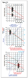
Here is a graphic that shows two pumps in series. You will not get exactly twice the head due to some resistence thru the pump itself. This also shows how the pump curve, defined by the manufacturer, works with the system curve (your system piping). At the point which the system curve and the pump curve cross, that becomes the OP operating point of the puymp.
In this example it changes as it is a solar drainback pump series. Once the fluid reaches the top of the collector, siphon is established, one pump turns off, and the single pump slide down the curve.
Attachments
- Status
- Not open for further replies.
Similar threads
- Replies
- 20
- Views
- 847
- Replies
- 4
- Views
- 1K
- Replies
- 2
- Views
- 265
- Replies
- 16
- Views
- 2K
- Replies
- 8
- Views
- 429