
Plumbing diagram comments?
- Thread starter SIERRADMAX
- Start date
-
Active since 1995, Hearth.com is THE place on the internet for free information and advice about wood stoves, pellet stoves and other energy saving equipment.
We strive to provide opinions, articles, discussions and history related to Hearth Products and in a more general sense, energy issues.
We promote the EFFICIENT, RESPONSIBLE, CLEAN and SAFE use of all fuels, whether renewable or fossil.
You are using an out of date browser. It may not display this or other websites correctly.
You should upgrade or use an alternative browser.
You should upgrade or use an alternative browser.
- Status
- Not open for further replies.
henfruit
Minister of Fire
BoilerMan
Minister of Fire
BravoWhiskey
New Member
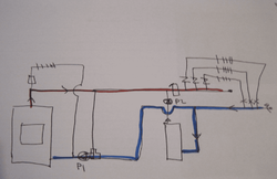
Maybe I'm not seeing it right, but it looks like to me that when one, the other, or both the pumps are running the water goes around the circuit above the oil boiler and there is nothing to cause the water to go through the zone valves and loads. Simple and effective would be to feed hot from wood boiler into supply side of oil boiler and draw return to wood boiler from return side of oil boiler and leave the existing oil boiler pump and circuits alone. Only downside would be that the oil boiler would be hot all the time and you could lose heat up the flue if the oil boiler is susceptible to that.Econoburn is going into the basement this afternoon and I'll begin plumbing this week. Looking for feedback before I start threading/sweating pipe. Thanks
Maybe I'm not seeing it right, but it looks like to me that when one, the other, or both the pumps are running the water goes around the circuit above the oil boiler and there is nothing to cause the water to go through the zone valves and loads. Simple and effective would be to feed hot from wood boiler into supply side of oil boiler and draw return to wood boiler from return side of oil boiler and leave the existing oil boiler pump and circuits alone. Only downside would be that the oil boiler would be hot all the time and you could lose heat up the flue if the oil boiler is susceptible to that.
It's my drawing. I see the problem. The circulator has to be on the supply side providing suction to the zones in order for the check valve to close. Do both circulators have to be identical in order for the swing check to fully close?
Bob Rohr
Minister of Fire
It's my drawing. I see the problem. The circulator has to be on the supply side providing suction to the zones in order for the check valve to close. Do both circulators have to be identical in order for the swing check to fully close?
With the boilers in Patallal you don'r need to connect the S&R, supply and return, at the right side of the drawing.
BravoWhiskey
New Member

It's my drawing. I see the problem. The circulator has to be on the supply side providing suction to the zones in order for the check valve to close. Do both circulators have to be identical in order for the swing check to fully close?
If it's not a problem to keep the the oil boiler hot all the time with the wood boiler all you have to do is run the supply from the wood boiler to the supply side of the oil boiler and likewise the return to the wood boiler hooks in somewhere on the return side of the oil boiler. If you need to avoid keeping the oil boiler hot all the time, here's the classic two boiler system, except in your case you would have a single load circulator and zone valves instead of the multiple circulators.
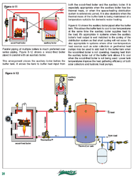
I think I got it now. I apologize for my design over the oil boiler. I'm trying to invision how it needs to be plumbed and that is how the existing plumbing is orientated. I have more room in my existing plumbing to install a 2nd return header in lieu of the supply. How does this look?
Attachments
BravoWhiskey
New Member
I'm pretty sure that's essentially the same as the one above that was borrowed from Tarm, and it should do what you want. I think it is important that they set it up so the wood boiler can circulate freely even when there is no load which should help avoid short cycling. Note that until the wood boiler is up to speed the load circulator can push water through the oil boiler, probably not a problem but you may want to think through how that affects your control strategy.I think I got it now. I apologize for my design over the oil boiler. I'm trying to invision how it needs to be plumbed and that is how the existing plumbing is orientated. I have more room in my existing plumbing to install a 2nd return header in lieu of the supply. How does this look?
Bob Rohr
Minister of Fire
I think I got it now. I apologize for my design over the oil boiler. I'm trying to invision how it needs to be plumbed and that is how the existing plumbing is orientated. I have more room in my existing plumbing to install a 2nd return header in lieu of the supply. How does this look?
You have the Econoburn piped as a primary loop, if in fact the red/ blue lines connect at the right hand side of the drawing? If you are zoning with zone valves there in no means for the flow to go to the zones. Just disconnect the red to blue line
")
The Tarm drawing shows pumps on the zones to move the flow, although they have the boiler pump and the zone pumps in series which will double the head when they both run, really no need to do that. The pump with or on the Themovar should have enough capacity to flow the boiler and the zones.
Attachments
Bob, doesn't that diagram force Hot water through the oil boiler when no zone is open? Won't it continiously circulate that way even if a zone opens?
Bob Rohr
Minister of Fire
Bob, doesn't that diagram force Hot water through the oil boiler when no zone is open? Won't it continiously circulate that way even if a zone opens?
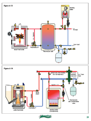
You do need some swing checks in the piping to prevent un-wanted flow. And expansion and fill valve. Also if you ever plan on adding a buffer, you would tie in the second boiler downstream from that. Fig. 6-14 is close, just eliminate the hydro-separator and add the zone valves to the header
Some good reading regarding series, parallel and separator piping in this journal http://www.caleffi.us/en_US/caleffi/Details/Magazines/pdf/idronics_10_us.pdf
Attachments
BravoWhiskey
New Member
If hydro separator is eliminated, and if no load, then flow through wood boiler stops as soon as return mix valve reaches setpoint. The Tarm design prevents this problem. Fig 14 with hydro separtor would work well.. Fig. 6-14 is close, just eliminate the hydro-separator and add the zone valves to the header
Bob Rohr
Minister of Fire
If hydro separator is eliminated, and if no load, then flow through wood boiler stops as soon as return mix valve reaches setpoint. The Tarm design prevents this problem. Fig 14 with hydro separtor would work well.
Good point, and it could provide some overheat dump protection if you leave the piping and separator uninsulated.
If hydro separator is eliminated, and if no load, then flow through wood boiler stops as soon as return mix valve reaches setpoint. The Tarm design prevents this problem. Fig 14 with hydro separtor would work well.
Correct me if I'm wrong, but doesn't the wood circ require constant circulation? Even when the mixing valve has reached it's setpoint? Hence the need for a primary loop? My revised diagram is similar to figure 14 with the exception of a loading unit in lieu of a mixing valve/circulator. I'm not ready to fund that kind of unit.
I'm pretty sure that's essentially the same as the one above that was borrowed from Tarm, and it should do what you want. I think it is important that they set it up so the wood boiler can circulate freely even when there is no load which should help avoid short cycling. Note that until the wood boiler is up to speed the load circulator can push water through the oil boiler, probably not a problem but you may want to think through how that affects your control strategy.
Doesn't the check valve in the supply of the oil boiler prevent this?
Bob Rohr
Minister of Fire
Correct me if I'm wrong, but doesn't the wood circ require constant circulation? Even when the mixing valve has reached it's setpoint? Hence the need for a primary loop? My revised diagram is similar to figure 14 with the exception of a loading unit in lieu of a mixing valve/circulator. I'm not ready to fund that kind of unit.
Doesn't the check valve in the supply of the oil boiler prevent this?
The pump on the wood boiler only needs to run if the boiler is up to temperature. I fire my pump/ mix valve assembly when the boiler reaches 140F, off at 130F. No need or reason to run that pump continously, especially after the fire burns out.
Best method is a buffer or storage, then the "tank" not the building becomes the load that the boiler sees.the sensor to run the boiler pump. I think it can be a big challange to run a wood boiler without some storage, especially on a multi zoned system.
To have a primary/ secondary piping the pumps are connected via closely spaced tees, and you need a pump in the primary loop.
M
mikefrommaine
Guest
You have the Econoburn piped as a primary loop, if in fact the red/ blue lines connect at the right hand side of the drawing? If you are zoning with zone valves there in no means for the flow to go to the zones. Just disconnect the red to blue line
The Tarm drawing shows pumps on the zones to move the flow, although they have the boiler pump and the zone pumps in series which will double the head when they both run, really no need to do that. The pump with or on the Themovar should have enough capacity to flow the boiler and the zones.
In this diagram what happens when the wood boiler is at temp and no zones are calling for heat? P1 would be running but it has nowhere to pump too, right?
Couldnt you connect the supply and return headers to creat a primary loop for wood boiler. Basically what the op originally posted... That then creates a situation where the zones don't get enough bc the water will flow through the oil boiler. The tarm diagram uses pumps to overcome this...
How about connecting the headers but also add another zone valve between the headers that is only open when there are no zones calling for heat. That way when there is a call for heat the new zone valve closes and directs the flow through the zones. And allows p1 to circulate water through the primary loop when there is no call for heat.
Would this be a normally open zone valve?
M
mikefrommaine
Guest
Thats what I was thinking. Maybe control it with the isolated end switches If you have something like a taco sr control.Would this be a normally open zone valve?
Bob Rohr
Minister of Fire
Thats what I was thinking. Maybe control it with the isolated end switches If you have something like a taco sr control.
A PAB pressure activated bypass valve could be used also, as the zone close down this valve "sheds" flow back to the return. no need for a zone valve or a electric accuator.e
Attachments
M
mikefrommaine
Guest
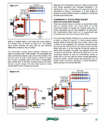
I think I hve the diagram finalized.
I'll use Econoburn's factory leads for the primary circulator (p2 on the drawing). This circulator will turn on with boiler @ 150. I have a honeywell 8148 aquastat relay now controlling the oil boiler. I'll remount this in the supply header after the oil boiler manifold and before the first zone branch. When a thermostat calls for heat, the zone opens and relays to P1 to circulate water to the zone. Theoretically, because HW is flowing, it shouldn't trigger the oil boiler to fire. I have to look into this and possibly adjust the settings. After water falls below 150, P2 shuts down and the oil boiler takes over normal operation. Any comments?
Do I need another make-up water line for the Econoburn?
Do I need another expansion tank? Probably adding another 60 gallons of water. Haven't done the math.
Attachments
ewdudley
Minister of Fire
I think I hve the diagram finalized.
I'll use Econoburn's factory leads for the primary circulator (p2 on the drawing). This circulator will turn on with boiler @ 150. I have a honeywell 8148 aquastat relay now controlling the oil boiler. I'll remount this in the supply header after the oil boiler manifold and before the first zone branch. When a thermostat calls for heat, the zone opens and relays to P1 to circulate water to the zone. Theoretically, because HW is flowing, it shouldn't trigger the oil boiler to fire. I have to look into this and possibly adjust the settings. After water falls below 150, P2 shuts down and the oil boiler takes over normal operation. Any comments?
Do I need another make-up water line for the Econoburn?
Do I need another expansion tank? Probably adding another 60 gallons of water. Haven't done the math.
Looking good. However by the book you might want to review the L8148 relocation. The failure mode effect of a P1 failure or a zone valve failed-shut state might result in the L8148 not being able to see high limit. You might prefer to add another aquastat in series and leave the boiler jacket aquastat alone.
my concern is the current 8148's location. It's mounted in the supply manifold a good 2' below the supply header. I don't know if this will see sufficient temps from the primary loop and prevent the oil boiler from firing.
ewdudley
Minister of Fire
Right, I'm saying to do it right you need two aquastats. The L8148 on the oil boiler supply should stay there as the boiler high-limit and failsafe, and another one to generate a call-for-heat to the oil boiler. If P1 fails the boiler has no high-limit and could sit there blowing steam for as long as make-up water is available.my concern is the current 8148's location. It's mounted in the supply manifold a good 2' below the supply header. I don't know if this will see sufficient temps from the primary loop and prevent the oil boiler from firing.
Edit: Also it looks like the oil boiler would cycle on and off the 150 degF setpoint according to the supply manifold temperature. More often the aquastat that enables the oil boiler is placed somewhere that senses the presence of wood boiler heat.
- Status
- Not open for further replies.
Similar threads
- Replies
- 5
- Views
- 614
- Replies
- 8
- Views
- 846
- Replies
- 8
- Views
- 1K
- Replies
- 24
- Views
- 656