Project - 12 volt 500watt benchtop power supply under 20 bucks

  • Active since 1995, Hearth.com is THE place on the internet for free information and advice about wood stoves, pellet stoves and other energy saving equipment.

    We strive to provide opinions, articles, discussions and history related to Hearth Products and in a more general sense, energy issues.

    We promote the EFFICIENT, RESPONSIBLE, CLEAN and SAFE use of all fuels, whether renewable or fossil.
Status
Not open for further replies.

jharkin

Minister of Fire
Oct 21, 2009
3,890
Holliston, MA USA
[ EDIT: I added some photo from my own thread, the lighting in my shop inst great for the camera however]


Thought I would post some photos of a quick build I did in case anybody finds this useful. If you have anything that runs on 12 volts DC and needs a lot of power you have probably noticed that commercial bench top power supplies can be very expensive.

There is a cheap and easy solution. Used high power computer server power supplies are dirt cheap on the surplus market, and can be modified for duty as a bench top supply with minimal work. What you want here are server supplies, not desktop supplies - the server units are built to provide big amps on 12VDC and not much else and they have exceptional voltage regulation.

I got the idea and modification information from radio control forums. Some intrepid folks figured out the pin outs for the hot swap connectors on a number of different units so once you know whats what its a simple matter to wire the unit to turn on and replace the hot swap connector with your favorite power connector.

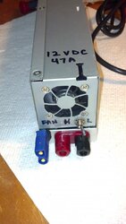
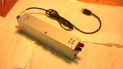
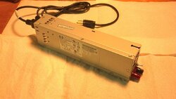
the unit below is an HP 1U server PSU that is rated to deliver 47amps on the 12VDC rail (so actually nearly 560 watts). It was probably hundreds of dollars new, I got a salvage unit on amazon for 10 bucks. An evenings work some parts from the local electronics dealer and presto - I have a nice bench top supply!
2013-07-19 09.36.47.jpg

2013-07-19 09.37.03.jpg


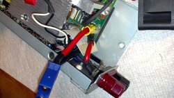
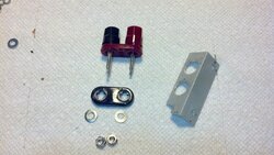
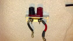
The small rocker switch is a Hi/Lo fan control, there is a fan sense lead and if you ground it it changes the fan from 100% duty to temperature control mode. The power supply on lead I just hardwired to ground so the unit is on whenever its plugged in. If you wanted to it could be wired to a switch. For the outputs, I removed the existing hot swap daughterboard that had blade connections and replaced it with a pair of bannana jack binding posts on a peice of angle iron wired directly to the +12v and GND terminals of the main board with 10awg wire and crimped ring terminals.

The bannana jacks are probably the weak link in terms of power delivery now (likely only good ofr 30A or less) so I will look at putting something heavier duty there before I try loading it to max amperage.


If your interested in exactly how its done let me know and I'll point you to instructions. RC users have modded a few different PSUs like this and some folks are even running pairs in parallel for nearly 100amps, or in series for 40+A @ 24v (running in series requires floating the DC ground on one unit, a little more involved work).

I will caution you thought that a lot of the folks on those RC boards really dont have a clue about electronics and its scary what some of them where trying to do - I had to really dig to find the right info to do this properly and safely. As with any project like this its not manufacturer approved and totally at your own risk of course.
 
  • Like
Reactions: woodgeek
You might be wondering, what do I need 47amps of DC power for?

Well here is the answer:


2013-07-19 09.39.02.jpg


In radio control, electric power is becoming very popular these days for everything up to large helicopters and airplanes (large defined as helicopters weighing well over 10lb with rotor diameters approaching 6 feet and airplanes with wingspans over 7ft). We use lots of high capacity lithium batteries - the biggest helicopters for example use massive packs up to configurations of 12 lithium cells (45 volts) at over 5000mAh (5.0 Ah) of capacity. Chargers are now out rated for up to and beyond 1000 watts (often needing 24v or even 30v input) so that we can recharge batteries that big in times as short as 15 minutes and even charge multiple batteries in parallel in similar time frames. To power these big chargers people use sets of deep cycle batteries in series or powerful benchtop DC supplies.

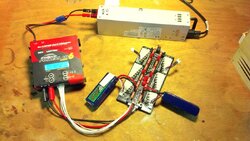
The new charger I got is called an FMA PowerLab6. Its a computer programmable multi-chemistry hobby charger rated for 40Amps @ up to 32VDC input for a max of 1000watts charging output on any battery type imaginable (NiCD, NiMH, NiZn LiIon/LiPoly/LiMn, LiFePo4/A123 systems, Lead Acid, etc) up to 24 volts. It can voltage boost and even charge a 24V battery running from a 12V supply, though at half the input amperage. I can charge anything from a flashlight to a cellphone to a car battery with it given the right adapter. My little bench top supply can actually only drive it to about half its potential at 12volts ~ maybe 480 watts ~ but that's more than enough for my needs right now.

--------------

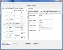
Note If you have a need to charge many different battery types and dont want to buy a lot of different chargers, one of these computerized hobby chargers is worth a look, even if you dont do RC hobbies. The unit I have allows you to program 25 custom charge profiles for any battery type.

One example - I already have a NOCO Genius 7.2amp 4 stage lead acid charger(bulk, absorb, float, equalize/desulphate). Its great for lead batteries but is very slow if I needed to do a full recharge on the car or the 100+ AH deep cycle in my backup sump pump. Rather than buy multiple NOCO chargers of various capacities I can use the Powerlab for the bulk charge and thus use the NOCOs equalization mode on any size lead acid.

For example on the sump pump I made a profile in the Powerlab to charge at 18Amps with a 14.5v absorb cutoff, then use the 4 stage NOCO to top it off and do an equalization. (I do this every couple months to keep the battery maintained, since the sump pump charger is a dump bulk charger) I created a simple car battery profile at 10A and 14.6v and a profile for small sealed 7Ah UPS batteries at 700mA and 14.7v.

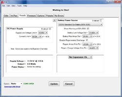
You can also define input power profiles in this thing, so for example you can tell it you are powering it from you car and set a current limit and voltage cutoff so it shuts down before discharging your car battery so far it wont start.


charger.jpg charger2.jpg
 
Yes - as a matter of fact, I was wondering what the need for this power supply was. Thanks for the explanation.;)
 
Thought I would post some photos of a quick build I did in case anybody finds this useful. If you have anything that runs on 12 volts DC and needs a lot of power you have probably noticed that commercial bench top power supplies can be very expensive.

There is a cheap and easy solution. Used high power computer server power supplies are dirt cheap on the surplus market, and can be modified for duty as a bench top supply with minimal work. What you want here are server supplies, not desktop supplies - the server units are built to provide big amps on 12VDC and not much else and they have exceptional voltage regulation.

I got the idea and modification information from radio control forums. Some intrepid folks figured out the pin outs for the hot swap connectors on a number of different units so once you know whats what its a simple matter to wire the unit to turn on and replace the hot swap connector with your favorite power connector.

the unit below is an HP 1U server PSU that is rated to deliver 47amps on the 12VDC rail (so actually nearly 560 watts). It was probably hundreds of dollars new, I got a salvage unit on amazon for 10 bucks. An evenings work some parts from the local electronics dealer and presto - I have a nice bench top supply!

View attachment 106572

View attachment 106573


The small rocker switch is a Hi/Lo fan control, there is a fan sense lead and if you ground it it changes the fan from 100% duty to temperature control mode. The power supply on lead I just hardwired to ground so the unit is on whenever its plugged in. If you wanted to it could be wired to a switch. For the outputs, I removed the existing hot swap daughterboard that had blade connections and replaced it with a pair of bannana jack binding posts on a peice of angle iron wired directly to the +12v and GND terminals of the main board with 10awg wire and crimped ring terminals.

The bannana jacks are probably the weak link in terms of power delivery now (likely only good ofr 30A or less) so I will look at putting something heavier duty there before I try loading it to max amperage.


If your interested in exactly how its done let me know and I'll point you to instructions. RC users have modded a few different PSUs like this and some folks are even running pairs in parallel for nearly 100amps, or in series for 40+A @ 24v (running in series requires floating the DC ground on one unit, a little more involved work).

I will caution you thought that a lot of the folks on those RC boards really dont have a clue about electronics and its scary what some of them where trying to do - I had to really dig to find the right info to do this properly and safely. As with any project like this its not manufacturer approved and totally at your own risk of course.

Would like to receive the information on building this.

Thanks
 
Just out of curiosity, do you know how accurate the power supply is, ie How close to exactly 12 volts does it stay?
Also, unfortunately, this is strictly 12 volts correct? Nice thing about a bench top model would be variable voltage.
 
You have some options with these units. By default it outputs about 12.5VDC if you don't do anything with the voltage adjust. One of the pins on the hot swap connector is a voltage sense lead and one experimenter figured out that you can hook it up to a 1K pot and get the unit to vary the output voltage between 11V and 13.8V. They did discover that it wouldn't do the full rated 47A if you upped the voltage.

You can also put 2 or more of these in series by isolating the DC ground on all but one unit and get 24V, 36V, etc.
You can also run them in parallel (this they are designed for and there is a current share pin) to get 94A @ 12V.
Ive seen at least one builder run 4 is series/parallel for 94A @ 24V (!!) but for that I think he need to hook them up to two dedicated 120V circuits to feed the beast.

And this is just for this one particular HP supply, there are lots of other models with different capabilities from Dell, Compaq, IBM, etc.


I'll add construction detail's later today... I have a bunch of saved notes and images from the build threads I read but I want to link back to the source rather than plagarise somebodies photo. Stay tuned.
 
To get you started here is some reading.

How to convert Server Power Supplies
Master thread about converting server power supplies on the radio control hobby website RCGroups. There is a lot to read and take it with a grain of salt - some of the experimenters there don't have a clue about electronics and really shouldn't be opening these things up. The early experimenters tried things like running them in series by disconnecting the AC ground and wrapping the case in electrical tape :( But the thread does have good information toward the end and good links to individual server supply models with detailed info.
The specific model I chose to convert is the HP DPS-600. I found one on amazon here.
There is a web page with a simple mod to this unit that doesn't even require opening the case here.

The mods I did where a bit more involved - details to follow.
 
OK, so here goes, I will try to keep this as simple as possible.

I bought an modified an HP DPS-600PB supply. Out of the box these units are equipped with a hot swap connector that hooks up to the server. You can do a quick and dirty mod just shorting a couple pins to turn it on then solder your favorite connector to the +12V and GND blades. This is documented on the here: https://sites.google.com/site/tjinguytech/my-projects/HP47A

There is a more detailed thread about this unit here. Based on info I gleaned from that site I opened up the unit and modified it internally.

http://www.rcgroups.com/forums/showthread.php?t=1581061

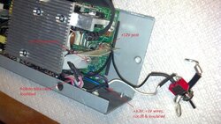
First thing you need to do is open the case. Unscrew the side and top panels. To get the top panel off you are going to have to peel off the plastic insulator that’s glued inside and unscrew the fan from the end cap. At the fan end of the unit you will see that the hot swap connector is mounted on a daughterboard that hooks up to the main board via:
  • 2 heavy aluminum straps bolted to +12VDC and GND posts on the mainboard
  • Individual wires for +3.3v and +5v
  • A ribbon data cable
Next thing you do is unbolt and remove that daughterboard. Disconnect the ribbon and cut oft the 3.3 and 5v wires.What you end up with will look something like this. Note that I have already modded the ribbon cable in the photo (next post).

2013-07-25 13.40.13.jpg


The experimenters on that board figured out how the pins on the hot swap map to the ribbon. The red wire of the ribbon is #1. We will be making some connections with that ribbon below.
PIN .......... Ribbon Wire ....... Description
. 1 ............ N/A ...................... +5VSB
. 2 ............ N/A ...................... +5VSB
. 3 ............ N/A ...................... +5VSB
. 4 ............ 3 .......................... Fan speed, ground for minimum speed. (For variable speed use ~4.6v to Vcc.)
. 5 ............ N/A ...................... -12V
. 6 ............ 5 .......................... PsKill, ground this and PsOn to turn on the PS.
. 7 ............ 6 .......................... +S (positive sense)
. 8 ............ N/A ...................... DC ground
. 9 ............ 8 .......................... -S (negative sense)
10 ............ 4 .......................... PsOn, ground this and PsKill to turn on the PS.
11 ............ 9 .......................... Current Share
12 ............ 7 .......................... Power OK/Fault (OK = 3.8V, Fault = 0V).
N/A .......... 1 .......................... Ground from the output board back to the main board (needs to be tied to DC ground).
N/A .......... 2 .......................... Ground from the output board back to the main board (needs to be tied to DC ground).
N/A ........ 10 .......................... Ground from the output board back to the main board (not needed).

Note that in all descriptions below, the red lead is wire #1 on the ribbon and the rest count sequentially.
 
To build a simple 12V supply

First I cut a piece of 3/4x3/4 angle aluminum to fit where the hot wwap was and drill it for the existing mounting posts and banana jacks. I mount the banana jacks and wire them to the +12VDC and DC GND posts on the main board with short lengths of 10AWG stranded auto wire with crimped on ring terminals. Not that its a very tight fit and I had to grind off some of the plastic from the banana backing plate.

2013-07-25 13.32.43.jpg2013-07-25 13.49.37.jpg

3.3v and 5v wires: Cut off and insulate (unless you want to use these voltages)

Ribbon cable:
  • Solder wires 1 (red),2,4,5 together and jumper to the ground post to turn on
  • If you want the fan to run constant, ground wire 3. If you want a high low control hook this to ground via a small SPST toggle switch. If you want variable control you can configure a pot – see details in thread.
  • Cut off and insulate the rest of the cable
Its a tight fit to get everything in there and clear the fan, when its done it will look something like this:

2013-07-25 13.59.10.jpg

To add adjustable voltage capability

These units have two voltage sense pins (wire 6 and 8 on ribbon) that would read the voltage on the server mainboard and control the 12V regulator. If you do nothing you get about 12.5VDC. If you want to adjust the voltage from 12VDC up to 13.8VDC, you can connect a 1Kohm pot from +5v to wire #8 of the ribbon cable. I think (not sure) that you can put the pot between +5 and wire #6 instead to adjust below 12V, or use a center tapped pot between 6 and 8 with the center tap to +5V to get adjustability up and down.

I have not tried any of this, so if you are interested I suggesting reading the thread in detail first.


To run 2 or more supplies in parallel for more current @ 12v

OTOB, these units have parallel run capability. Just build two units with the +12v to +12v and GND to GND, then connect wire #9 on the ribbon cable of each unit together. This is the current share pin and will configure the units to split the current load equally.

To run 2 or more units is series for 24V, 36V, etc.

This is the tricky mod. OTOB the AC and DC grounds of these units are tied together and bonded to the case. For 24v, what we need to do is float the DC ground on the “high unit” and then hook them in series (so +12v of unit A connects to DC GND of unit B, and the +12v of unit B is your +24 output). For more than 24volts just keep adding units in series and make sure that only one unit has a bonded ground.

This image from the main thread shows the circuit board mods you need to do to float the ground.
http://www.rcgroups.com/forums/showatt.php?attachmentid=4580912&stc=1

Once setup this way you can use both 12v and 24 volt outputs. For the 12volt output only tap the grounded unit – if you tap the floated unit and accidentally ground any connected DC device you will short out the PS.
 
OK, so as I mentioned above I wanted to add a higher current connector since I think the bananas are only good up to 30amp or less. I did this mod to add a second output using an EC5 connector, which is a hobby battery connector rated for 120amps. I use this to hook up my fancy new charger, leaving the banana's free for other uses (I have a few other older chargers as well). you can get "stackable" banana's and run mutliple units off one set of binding posts.

2013-07-25 14.11.35.jpg


I think I need to join battery chargers anonymous :( I just counted them and between hobby, automotive, tool and household I have at least 10 different DC and AC battery chargers!!!
 
I've been thinking about doing just this very thing for use with ham radio equipment. The radios run on 12 volts, and depending on transmit power, can pull a lot of amps.

I think using a server power supply is a great idea for a few reasons:
1) Rated for continuous duty
2) Clean power (dirty power causes all sorts of problems in computer systems)
3) Designed for heavy 12v loads for servers full of disk drives
4) Readily available
5) Should also have 5v and 3v outputs. (USB is 5v, so it could drive USB power ports easily)

You could mount that supply out of sight under the bench somewhere and run one of these rig-runner distribution blocks up top.

http://universal-radio.com/catalog/hamps/2231.html

The "power pole" connectors are pretty popular with hams, and make it really easy to connect/disconnect equipment. They also keep others from accidentally plugging things in backwards.

http://universal-radio.com/catalog/hamps/powerpole.html

-SF
 
Very interesting, and well written, Jeremy! I am thinking about building one of these just to have for different gadgets.
Thanks for sharing!
 
Status
Not open for further replies.