
New Toy for Huffdawg!
- Thread starter huffdawg
- Start date
-
Active since 1995, Hearth.com is THE place on the internet for free information and advice about wood stoves, pellet stoves and other energy saving equipment.
We strive to provide opinions, articles, discussions and history related to Hearth Products and in a more general sense, energy issues.
We promote the EFFICIENT, RESPONSIBLE, CLEAN and SAFE use of all fuels, whether renewable or fossil.
You are using an out of date browser. It may not display this or other websites correctly.
You should upgrade or use an alternative browser.
You should upgrade or use an alternative browser.
- Status
- Not open for further replies.
jebatty
Minister of Fire

willyswagon
Burning Hunk
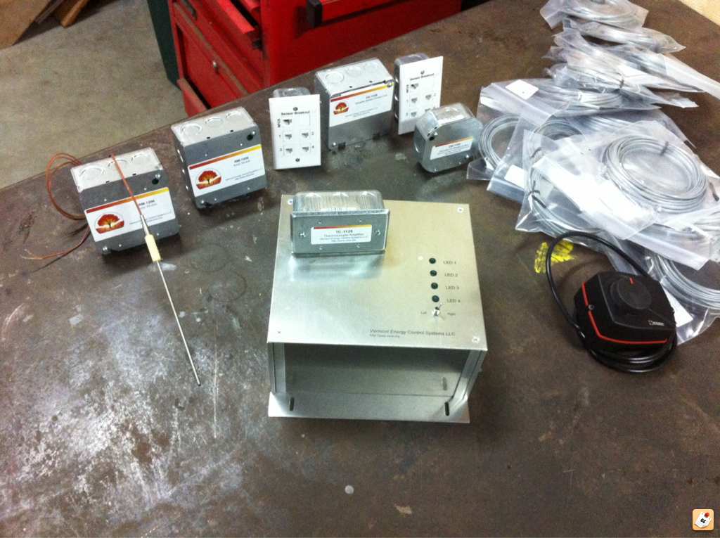
Oh-kay ........
Recognize the electrical box enclosures
the rest- not so much
is that a rectal thermometer on the left ?
Ya I'm looking at that gear and I'm thinking, I'm not going to go play there if that's what he calls "A New Toy!"
Coal Reaper
Minister of Fire
I got that black box with dial on the right, wish I had the rest of it too. How are you using the 4 way valve control?
I have a 150 gal. hydraulic separator and 1000 gals. storage. My 4 way valve is between them its plumbed like the drawing above. as suggested by Bob Rohr
Nofossil
Moderator Emeritus
Gee - that hardware looks kinda familiar ;-)
Can't wait to see it installed and running. Good luck with it, and thanks for sharing.
Can't wait to see it installed and running. Good luck with it, and thanks for sharing.
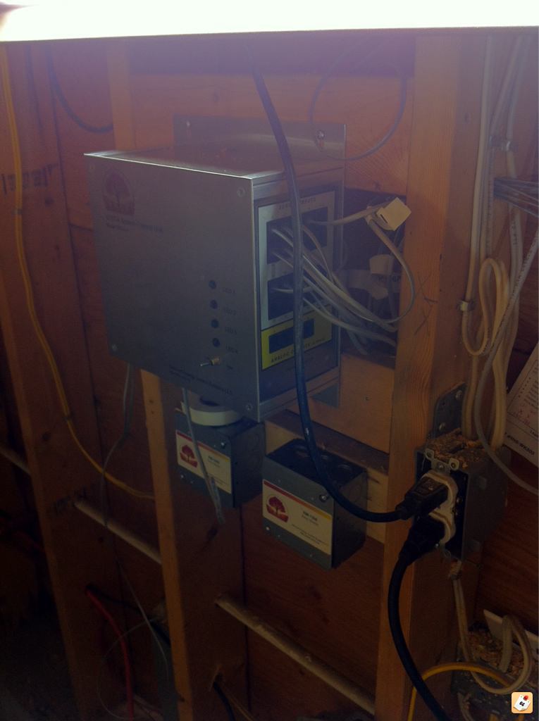
I have been hummin and hawing the last few days trying to decide where I'm going to install. It will be installed in a Harry Potter sort of room underneath a stairwell that is adjacent to the boiler room . There is the odd 110v conductor running in the stud bays where I want to install hopefully they won't interfere with the contoller operation.
Nofossil
Moderator Emeritus
Shouldn't be a problem. I'd avoid running sensor cables alongside power lines for long distances, but even that's more of a precaution than a requirement. If you want to use the front panel LEDs as status indicators or use the front panel switch for manual mode setting (Winter / Summer, for instance) then you'd want to put it where you can see it and get to it easily. Otherwise, it really doesn't matter.
Huff, While I don't recommend it, I have a 50 foot underground run of 2 inch conduit in which I run 8 sensors, 4 digital outs, 2 ethernet cables along side a 12 gauge 120 volt feed. I've had no problems with this. Also the longest runs I have for sensor and digital cables is 125 feet. Again no problems with this. Very reliable and robust system.
Nofossil
Moderator Emeritus
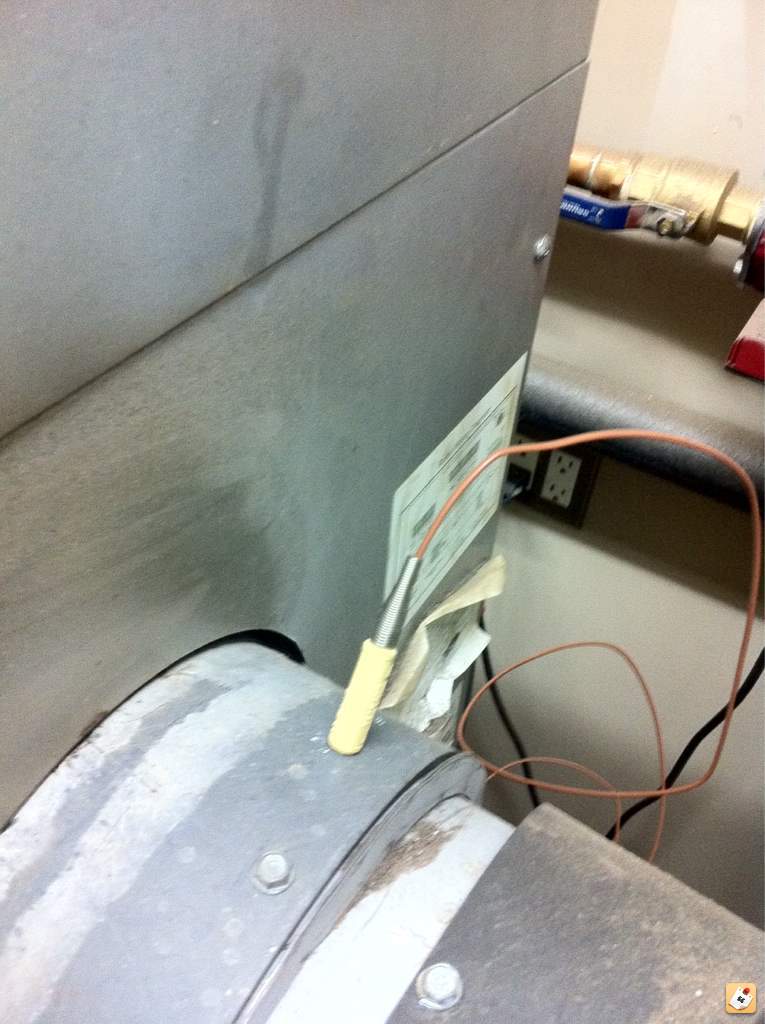
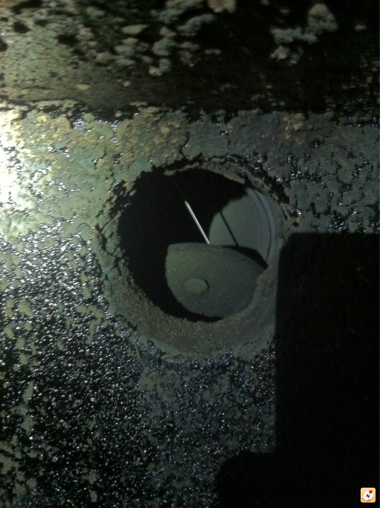
Nice! I'd pull the thermocouple back a couple of inches so that the tip is nearer the center of the flue and so that the molded 'handle' isn't touching the hot metal.
mr.fixit
Feeling the Heat
mr.fixit
Feeling the Heat
No . The boiler is stand alone. But there is a few thing u could control on the boiler if wanted to.
Nofossil
Moderator Emeritus
I'm a bit more hard-core than most (and maybe more than is prudent). I control the blower, the main circulator and the bypass circulator on my EKO with mine. Huff's approach is more reasonable - let the boiler do its own thing, but manage the heat loads and storage to optimize the boiler's operation.
Here's a chart from last season where I'm controlling the EKO fan (fan scale is % of full speed) to try and hold 1100 degrees combustion temp (combustion temp is divided by 10 to fit on the scale). You can see the purge cycles - have to do that every so often to avoid puffing when running at reduced fan speed.
While this is possible, I'd regard it as experimental. Varying circulator speed to maintain outlet temp is a lot more straightforward.
Last edited:
I would suggest that the VECS controller can provide much better control of the boiler than the standard EKO controller.
The VECS can monitor stack temperatures, input and output water temperatures and make appropriate adjustments to fan speed to optimise the burn.
The VECS can monitor stack temperatures, input and output water temperatures and make appropriate adjustments to fan speed to optimise the burn.
Nofo. Is the graph showing a max temp of 550f for flue tempI'm a bit more hard-core than most (and maybe more than is prudent). I control the blower, the main circulator and the bypass circulator on my EKO with mine. Huff's approach is more reasonable - let the boiler do its own thing, but manage the heat loads and storage to optimize the boiler's operation.
Here's a chart from last season where I'm controlling the EKO fan (fan scale is % of full speed) to try and hold 1100 degrees combustion temp (combustion temp is divided by 10 to fit on the scale). You can see the purge cycles - have to do that every so often to avoid puffing when running at reduced fan speed.
While this is possible, I'd regard it as experimental. Varying circulator speed to maintain outlet temp is a lot more straightforward.


Nofossil
Moderator Emeritus
Nofo. Is the graph showing a max temp of 550f for flue temp
Nice! Good to see a screen capture. Have you played with datalogging? If you go to the 'Logs' tab and click on any date, you'll get a spreadsheet of all the temps, inputs, outputs, and variables for the day in one minute increments. You can use Excel (or OpenOffice) to make pretty graphs to see what happened.
Yes, that's 550 degrees flue temp. I have the EKO 25 which has very short HX tubes, leading to higher flue temps than other boilers :-(
Note that this measurement is VERY different from what you get with the magnetic stick-on flue temp gauges. My magnetic gauge never goes above 250.
I'm also not sure how well calibrated the thermocouple is. I rely on the mathematics of the circuitry since I don't have a high temperature reference standard, but a second commercial thermocouple gives very similar numbers.
Part of the reason I'm playing with fan control is to lower the velocity of the flue gasses through the HX tubes and maybe capture an occasional BTU that might have escaped otherwise.
- Status
- Not open for further replies.
Similar threads
- Replies
- 6
- Views
- 776
- Replies
- 6
- Views
- 450
- Replies
- 6
- Views
- 398
- Replies
- 13
- Views
- 470
- Replies
- 1
- Views
- 246