Garn hydronic design

  • Active since 1995, Hearth.com is THE place on the internet for free information and advice about wood stoves, pellet stoves and other energy saving equipment.

    We strive to provide opinions, articles, discussions and history related to Hearth Products and in a more general sense, energy issues.

    We promote the EFFICIENT, RESPONSIBLE, CLEAN and SAFE use of all fuels, whether renewable or fossil.
go to flatplateselect.com GEA makes all sorts of cool sizes, like 5x20 heat exchangers that will give you really close approach temps.

If you want, PM me with your outputs from flatplateselect.com and I'll look over them for you to make sure things make sense.
 
go to flatplateselect.com GEA makes all sorts of cool sizes, like 5x20 heat exchangers that will give you really close approach temps.
if you want, PM me with the outputs from there and I'll look them over to make sure they make sense.
 
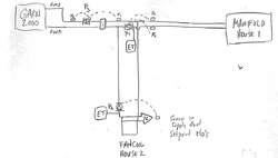
If you do the Logstor 1.5" you have a better situation than 1.5" Uponor. 1.5" logstor has an ID of 1.6" ID, better than the number I was using. if you do to and from the GB with 1.5" to house #1, you have a head loss of 11' at 600LF of pipe and 15 GPM.
that's way better.
house 2 at 600 feet would need lower flow rate most of the time, as the floor loops can mix the temp down to 100F probably.
you won't use one pump to pump the entire 900 feet with house 2, you'd use one pump to move the 600' of 1.5" pipe, and do as maple suggested, connect a pair of closely spaced tees with another circulator pushing thru the floor loops when there is a heat call for any particular zone. or you use a flat plate heat exchanger in the building (could be either the GB or house 1) and run the heating loops pressurized. (as a contractor this is what I would do, because if there are air problems in the floor loops, I have to go back and fix it and that costs the price of a heat exchanger the first time I have to go back.)

on a separate topic, while you're waiting for Dan's books (and they're worth the wait, if nothing else, for the pickle story) read Caleffi's Idronics series. google them (they're free PDFs) and read them in order, and you'll have a really decent handle on what is going on in hydronics. the ones that deal with topics you don't particularly care about, just skim and look at the nice pictures.

cheers,
karl
I did read both of Dan's books and idronics and I have to say that, considering the 23' rise on the highest point of house 1 along with the benefits of a closed and pressurized system, I makes sense to go ahead and pressurize in the Garn Barn.

On another note, I inquired what size fittings come on the logstor 1.5" dualpex (1.6" ID) and I was told the compression fittings are 1-1/2" MPT. I'll have to call back to clarify that there is no bottleneck because the submittal sheet for uponor's version of 1-1/2" MPT indicates the ID of 1-1/2" WIPEX MPT compression fitting is 1.24" which would create a bottleneck in 4 places, right? One bottleneck at each end of both underground lines. How much this would impact the system's performance?

Since I'm trying to maximize the system's performance, I'm reconsidering trench and foam. 2" hepex with 2" WIPEX (both ID 1.6") would eliminate the 1.24" bottlenecks. The trench and foam method would take longer but seems that it could be better - more R value, less head loss, and more maneuverable. I'm 99% certain I can make it water-tight. I'll post the bluemax/fiber/XPS demonstration when I get time later today. How much of a difference in performance would I see having the 2" WIPEX over 1-1/2" WIPEX?
 
Last edited:
either will be fine. the ID over the long distance is what's going to kill you. the couple restrictions in the joints won't matter. the 2" hepex and foam will be cheaper by a long shot than the 1.5" logstor. and probably just as good if your ground doesn't move much if at all.

I don't know what wipex is, but 1.5" ID smooth pipe for 600' at 10 gpm and 30 deg delta T = 150,000 btu and 5.5' head.
1.25" ID smooth pipe for 600' at 10 GPM and 30 degree delta T= 150,000 btu and 12 feet head.
1.00 ID smooth pipe for 600' at 10 GPM and 30 degree delta T= 150,000 btu and 31 feet head.

I'd split the difference and get the 1.25, and use a Taco 0015 on high or viridian VT 2218. for each zone with the check valve between the supply and return tees as above, and a 0015 on low to keep the pipes hot and move water thru the DHW HX. when one or both the Fan coils turn on, it'll add it's head to the slow 0015 primary circulator, but use minimal energy for the 24-7 pump, and not start pumping cold water thru the air coils. it'll have hot ready for you.
 
  • Like
Reactions: Antman
For my underground lines, I think I'll use 2" Hepex (1.629" ID) for house 1 (500' primary loop) because it really isn't that much more expensive than the 1.5" Hepex (1.244" ID). I already have 1.25" Hepex (1.054" ID) for house 2 (600' primary loop). My plan is to wait until spring or summer to trench and foam both underground runs when the outside conditions are optimal (dry and 85F). In the meantime, can anyone suggest the best way to bring the lines into the attic through a wooden soffit? I am anticipating 2-3' lengthening of the hepex at 180F for each home. I'm curious if this lengthening and expansion of the underground lines disrupts the closed cell polyurethane foam (PUF) in a trench and foam application any more than the pre-insulated products? I plan to do as Tennman suggested with 6mil plastic (1' wide by 2' deep trench, high voltage line in the bottom, backfill, 6mil plastic, 4" PUF, lay down lines, additional 4" PUF, overlap 6mil plastic and waterproof the joints using blumax/fiber, goal is 1' x 1' x 550' = 550 cu ft or 6,600 board feet PUF for both runs combined).
 

Attachments

  • Garn design 1-p1.jpg
    Garn design 1-p1.jpg
    222.4 KB · Views: 433
  • IMG_2724.JPG
    IMG_2724.JPG
    14.8 KB · Views: 344
Last edited:
Thanks for the interest -- 23 days of riding, 25 days total. Shortest mileage day was 23 and longest was 97. Average/day was 65 miles. Temperatures ranged between a low of 28F (two mornings) and a high of 94F. The trip was solo, self-supported. Bicycle plus packs, gear, food, water was about 105 pounds. An amazing adventure for a 66 year old guy. This link covers a quick summary of most of the trip: Rolling

I am narrowing down on a destination for another trip in 2016.
Head to San Diego. I can connect you with a ton of folks older than you, all training as if they are heading to the Tour:).
 
For my underground lines, I think I'll use 2" Hepex (1.629" ID) for house 1 (500' primary loop) because it really isn't that much more expensive than the 1.5" Hepex (1.244" ID). I already have 1.25" Hepex (1.054" ID) for house 2 (600' primary loop). My plan is to wait until spring or summer to trench and foam both underground runs when the outside conditions are optimal (dry and 85F). In the meantime, can anyone suggest the best way to bring the lines into the attic through a wooden soffit? I am anticipating 2-3' lengthening of the hepex at 180F for each home. I'm curious if this lengthening and expansion of the underground lines disrupts the closed cell polyurethane foam (PUF) in a trench and foam application any more than the pre-insulated products? I plan to do as Tennman suggested with 6mil plastic (1' wide by 2' deep trench, high voltage line in the bottom, backfill, 6mil plastic, 4" PUF, lay down lines, additional 4" PUF, overlap 6mil plastic and waterproof the joints using blumax/fiber, goal is 1' x 1' x 550' = 550 cu ft or 6,600 board feet PUF for both runs combined).
it'll add a little pipe, but make a large wide arc with the piping. the bottom of that run will move quite a bit, and turning that 90 up the wall won't help.
swing the pipe out from the wall at 90 degrees to the eventual direction, and curve it toward the other end point, and that arc will absorb a lot of that expansion. a piece of drain tile or 2 around it in that are will provide some air space for the pipe to push against rather than just soil. that's just thinking, not something I've ever had to do. I've always had enough curves in the pipe that it could move a little.
karl
 
I have a 500' primary loop which is predominately underground. I think I can use 1-1/2" hepex but I am trying to determine if 2" hepex to minimize head loss in this long loop could possibly be too large? On page 15 of the Garn Design Manual a 2" nominal plastic pipe intersects 0 at what appears to be ~12 GPM and ~1 or 2 FPS. Does this mean I can only operate the primary circ at 12 GPM or higher? What problems would I have with velocities of less than 1 FPS?
 
bubbles will collect at high spots. There is such a thing as too big a pipe. it may not cause you any problems, depending on lots of things like how your system is piped and where you have air elimination points. or it may.
 
Once you drop below 2 fps,the water doesn't entrain the air bubbles as well and getting all the small micro-bubbles purged may be a challenge, especially if you have any ups and downs in the piping. If the small bubbles collect and form a large bubble you could get an air lock.
 
either will be fine. the ID over the long distance is what's going to kill you. the couple restrictions in the joints won't matter. the 2" hepex and foam will be cheaper by a long shot than the 1.5" logstor. and probably just as good if your ground doesn't move much if at all.

I don't know what wipex is, but 1.5" ID smooth pipe for 600' at 10 gpm and 30 deg delta T = 150,000 btu and 5.5' head.
1.25" ID smooth pipe for 600' at 10 GPM and 30 degree delta T= 150,000 btu and 12 feet head.
1.00 ID smooth pipe for 600' at 10 GPM and 30 degree delta T= 150,000 btu and 31 feet head.

I'd split the difference and get the 1.25, and use a Taco 0015 on high or viridian VT 2218. for each zone with the check valve between the supply and return tees as above, and a 0015 on low to keep the pipes hot and move water thru the DHW HX. when one or both the Fan coils turn on, it'll add it's head to the slow 0015 primary circulator, but use minimal energy for the 24-7 pump, and not start pumping cold water thru the air coils. it'll have hot ready for you.

I appreciate your idea of constantly circulating through two 5x12(20) FPHX with a 0015 on low. Could you look at my redrawing to clarify if this is what you were describing? Also, if I were to go ahead and put the water to water FPHX at the highest point in the system, couldn't I put air vents on both sides of it ( a manual one on the open side and an automatic on the closed side) to take care of any problems with air lock associated with the low velocity on the open side that comes with using 1.6" ID buried pipe?
 

Attachments

  • GHD-p1 copy.jpg
    GHD-p1 copy.jpg
    114.1 KB · Views: 279
I appreciate your idea of constantly circulating through two 5x12(20) FPHX with a 0015 on low. Could you look at my redrawing to clarify if this is what you were describing? Also, if I were to go ahead and put the water to water FPHX at the highest point in the system, couldn't I put air vents on both sides of it ( a manual one on the open side and an automatic on the closed side) to take care of any problems with air lock associated with the low velocity on the open side that comes with using 1.6" ID buried pipe?
if your primary loop is short, I think you'll be fine. the parasitic losses of a long piece of pipe like that will be high.
really I was thinking that your whole distribution system in the house you wanted to be open. your design as planned would probably work fine (without looking at it too closely) I would move the return sensor on the 0013 VDT closer to the Flat plate hx. it'll respond really slowly as is.
karl
 
Many thanks to the great guidance here. I am firming up my design and looking to trench and foam in 10mil plastic wrapped and sealed with bluemax liquid rubber as soon as the outside temps are ideal (at least 85F). I need to clarify one more thing and is has to do with the supply pump. Is there any reason I can't place it 250' from the Garn hot water supply (HWS) where the pipe comes back out of the ground and into the FPHX? If this is possible, is there a minimum distance a pump can be from the FPHX? I'm assuming not, because I've never come across a minimum distance on a distribution side. Just wanted to get feedback from the experts on this issue or any other concerns with my schematic. Thank You.
 

Attachments

  • image.jpeg
    image.jpeg
    108.4 KB · Views: 283
Hello Antman,

Contacting a hydronic circulator specialist at B+G or TACO and go from there as you can very easily
put your circulator on a reversing timer to push the same water back and forth using a smaller single pipe pex in insulated solid ADS tubing

Chatting wit B+G or TACO sales representative is going to solve this for you the first time and avoid spending extra money.

This is the only way your going to solve your current piping issues. I would also upload your
drawings to www.heatinghelp.com if you are now a member.They are all plumbers
over there and will help you too.
 
Last edited:
Many thanks to the great guidance here. I am firming up my design and looking to trench and foam in 10mil plastic wrapped and sealed with bluemax liquid rubber as soon as the outside temps are ideal (at least 85F). I need to clarify one more thing and is has to do with the supply pump. Is there any reason I can't place it 250' from the Garn hot water supply (HWS) where the pipe comes back out of the ground and into the FPHX? If this is possible, is there a minimum distance a pump can be from the FPHX? I'm assuming not, because I've never come across a minimum distance on a distribution side. Just wanted to get feedback from the experts on this issue or any other concerns with my schematic. Thank You.
Generally, you'll want the circulator as close to the GARN as possible. There is math in the Garn design manual for calculating out the NPSH available for your circulator in any location. I would keep the circulator (unless there is some other overpowering reason) as close to the GARN as possible. The GARN in your place is the point of no pressure change, and you want to pump away from that, and as close as possible to it.

off hand, I'd throw a check valve in the primary loop between the supply piping and the return piping. this will keep the supply piping from pulling backwards thru that connection. and make sure you have flow checks in all the branch circulators.
 
  • Like
Reactions: hobbyheater
I just did my first set of foamed in place lines, (copper) and the price was really reasonable compared to logstor or anything else. the 1.5" uponor with EP fittings would be fine. 2" might be even better, at a couple bucks a foot higher price. the foam ran about $5 per foot. plus $8? per foot for 1.5" pex ($4x2) for $13 a foot you have durn good insulation, durn good flow.

keep the circulator near the boiler to remove issues with the NPSH on that circulator, and that will help too.
the 2000 is a little small for that load, but most of the year it'll handle all the load, and part of the year it'll handle most of the load.
karl

also, zoning with small circulators in the basement to deliver to the house air coils will help them self purge should a little air get in them.

So I have spray foam contractor who is going to help me trench and foam closed-cell PUF next month, but he doesn't want to spray into plastic for some reason and recommends spraying into tyvek house wrap. So rather than fighting with trying to add a layer of plastic around the foam for additional waterproofing, I have decided to spray directly into the ground.

The frost line here is 1' and the water table is listed at 1', although the 2 houses and the trench are on high ground (10-20' higher the the surround farmland) so I doubt the trench will ever be under water. To make it easy on everyone when it comes time to spray, I plan to suspend two 2" hepex lines at 18-20" deep using stakes on either side of a 1' wide x 2' deep trench. At the very bottom of the trench I'll put a 2" electrical conduit for high voltage and two 1" hepex lines for hot and cold water. Then, spray foam the entire bottom half of the trench which puts all the foam below the frost level and gives me a 1'x1' block of closed-cell PUF below any potential ground heaving which really isn't an issue in our relatively warm climate anyway (i.e. 18 degree F day). After the foam has cured, I will add a 1" irrigation tubing for control wiring before backfilling.

My question is this... should I add sand in the trench?

We are near the New Madrid fault line, but otherwise the ground is mostly clay and unlikely to move. I'm just trying to decide if the extra effort of adding sand is worth the risk of attracting water to my PUF block that I'd like to keep dry
 

Attachments

  • 2016-09-26 13-03-18.jpg
    2016-09-26 13-03-18.jpg
    66.7 KB · Views: 223
Last edited:
I don't think sand will draw water but rather let water drain away.

Our pond had a sand vein and would never stay full. Until the day we dug it out and repack the trench with clay. The clay is holding all our water in now. Pond level is up 2' now.

Sent from my SM-G900V using Tapatalk
 
So I have spray foam contractor who is going to help me trench and foam closed-cell PUF next month, but he doesn't want to spray into plastic for some reason and recommends spraying into tyvek house wrap. So rather than fighting with trying to add a layer of plastic around the foam for additional waterproofing, I have decided to spray directly into the ground.

The frost line here is 1' and the water table is listed at 1', although the 2 houses and the trench are on high ground (10-20' higher the the surround farmland) so I doubt the trench will ever be under water. To make it easy on everyone when it comes time to spray, I plan to suspend two 2" hepex lines at 18-20" deep using stakes on either side of a 1' wide x 2' deep trench. At the very bottom of the trench I'll put a 2" electrical conduit for high voltage and two 1" hepex lines for hot and cold water. Then, spray foam the entire bottom half of the trench which puts all the foam below the frost level and gives me a 1'x1' block of closed-cell PUF below any potential ground heaving which really isn't an issue in our relatively warm climate anyway (i.e. 18 degree F day). After the foam has cured, I will add a 1" irrigation tubing for control wiring before back filling.

My question is this... should I add sand in the trench?

We are near the New Madrid fault line, but otherwise the ground is mostly clay and unlikely to move. I'm just trying to decide if the extra effort of adding sand is worth the risk of attracting water to my PUF block that I'd like to keep dry
=====================================================================================================

The NEC requires electrical conduit above the water lines if my memory is correct, normally its in separate two trenches with high voltage (600Volts +)

The P waves (pressure waves) from an earthquake will liquify clay soils in a heartbeat, so its a question of what is an acceptable risk fo you with your trench?

Bedding a utility of any kind on a layer of sand is simple easy insurance.

The Tyvec is just another layer of insurance for you pipe and conduit run. It would be simple enough to build a box frame on caster wheels to hold it in place as he sprays the foam and move it up as the work progresses.
 
So I have spray foam contractor who is going to help me trench and foam closed-cell PUF next month, but he doesn't want to spray into plastic for some reason and recommends spraying into tyvek house wrap. So rather than fighting with trying to add a layer of plastic around the foam for additional waterproofing, I have decided to spray directly into the ground.

The frost line here is 1' and the water table is listed at 1', although the 2 houses and the trench are on high ground (10-20' higher the the surround farmland) so I doubt the trench will ever be under water. To make it easy on everyone when it comes time to spray, I plan to suspend two 2" hepex lines at 18-20" deep using stakes on either side of a 1' wide x 2' deep trench. At the very bottom of the trench I'll put a 2" electrical conduit for high voltage and two 1" hepex lines for hot and cold water. Then, spray foam the entire bottom half of the trench which puts all the foam below the frost level and gives me a 1'x1' block of closed-cell PUF below any potential ground heaving which really isn't an issue in our relatively warm climate anyway (i.e. 18 degree F day). After the foam has cured, I will add a 1" irrigation tubing for control wiring before backfilling.

My question is this... should I add sand in the trench?

We are near the New Madrid fault line, but otherwise the ground is mostly clay and unlikely to move. I'm just trying to decide if the extra effort of adding sand is worth the risk of attracting water to my PUF block that I'd like to keep dry

You'll find probably that any sort of material is better than bare ground. the foam gun will blow around all sort of dirt etc, contaminating the foam. My guy won't spray onto bare ground. tyvek would be OK I guess. He's probably melted regular poly with the curing temperature of the foam.

I'd do the electrical off to the side, but still at least 18" to the top of conduit, more under a driveway. I always run extra conduits etc.
sand is OK for drainage, but I'd use pea gravel or 3/4" washed rock if you have it available. but make sure you're not draining it towards your house.

karl
 
It's been a long summer and we installed underground lines and built a chase to get 2" Hepex into the attic. The Hepex was converted to 1-1/2" Hepex once in the attic. We are planning to build the manifold at the highest point in the attic.

Will the manifold diagrammed here hydraulically separate the primary and secondary?
 

Attachments

  • Garn Design.jpg
    Garn Design.jpg
    117.4 KB · Views: 297
It's been a long summer and we installed underground lines and built a chase to get 2" Hepex into the attic. The Hepex was converted to 1-1/2" Hepex once in the attic. We are planning to build the manifold at the highest point in the attic.

Will the manifold diagrammed here hydraulically separate the primary and secondary?
yes, but it will not necessarily separate the secondaries from each other. to do that you want to get the manifold flow rate under 2 feet per second flow rate at full flow minus one load.
 
At design conditions (100,000 BTUH) when all 3 furnaces are calling for heat, the primary flow rate is 10 GPM and the secondary flow rates are:

zone 1 (WTAHX) = 2.5 GPM
zone 2 (WTAHX) = 3.33 GPM
zone 3 (WTAHX) = 4.17 GPM

So, if I understand you correctly, "full flow minus one load" (i.e. minus zone 1) = 7.5 GPM

referencing http://www.engineeringtoolbox.com/pressure-loss-steel-pipes-d_307.html

7.5 GPM through 1-1/2" steel pipe is ~1.24 f/s
7.5 GPM through 2" steel pipe is ~0.74 f/s

Additionally, I am planning 4 other zones:

DHW + sidestream towel warmer with monoflow tees and trv (constant flow, entire heating season)
pool (shoulder seasons)
spa (entire heating season)
garage fancoil (only around design conditions which is 18F)

I guess I need to calculate these additional flows but it looks like I'll be building the manifold using 2" tees and nipples to try to hydraulically separate the secondary loads.

Am I on the right track? Also, where do you get the 2 ft/s because I referenced 4 ft/s from Caleffi?

Thank you
 
Last edited:
Could I please get suggestions/feedback on my thoughts for boiler and primary pumps:

P1 --> 0013-VDTF3 (cast iron delta T) for house 1 primary in Garn Barn --> [email protected]
P2 --> VT2218-HY1-4C1A00 (cast iron setpoint) for fancoil in house 2 --> [email protected]
P3 --> 0010-VSSF3 (stainless steel variable speed setpoint) for the Garn boiler --> up to 18GPM@4FOH (only uses S1) setpoint setting ~180F

OR

P3 --> 0013-VDTSF3 (stainless steel delta T) for the Garn boiler --> up to 18GPM@4FOH (uses S1 and S2) dT setting 5F
 

Attachments

  • boiler and primaries.jpg
    boiler and primaries.jpg
    54.6 KB · Views: 205
Last edited:
With three circulators as you suggest in the drawing your going to
have issues with the point of no pressure change even though you
do not have an air scoop and lots of air bubbles even though its an open system.

A little help from a B+G or TACO sales rep will solve this for you if you fax them a
drawing or drawings of your system.

Your trying to circumvent basic laws of hydraulics with your design and your going to lose circulators.