Just so ya know, take my advice with salt. I am just a fella who likes the DYI approach too. I had a pretty big (not dangerous) fail prior to getting an Eko boiler. Failed the research and engineering part.
That is a rather unique design you have built from. Is it all yours? Now I see why you have the oddball temps at the ports. You sure do have the welding skills, kudos to ya.
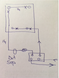
To me, supply from the top and return below is logical. So, I would do #3 but reversed. Combining both lower ports and both upper ports should help in keeping the top hotter than the bottom, instead of a criss-cross or side-to-side fashion.
If your plan includes a larger FPHX that has less head loss and you move it to the boiler shed, you should see big gains in the boiler loop efficiency. The results may put a damper on the new storage loop. If your storage loop is pressurized, no problem. If on the other hand it is unpressurized will you be able to get the flows needed to take all of what the PFHX is providing at 200F? Without the cavitation issue moving to that side? Maybe your original HX will keep up if you throttle back on the boiler output. I know you stated you wanted the big numbers in storage.
190-200F water temps in the boiler at regular operation, holy cripes. Is that how the owb fellas go? Those temps in storage will be sure to keep your garage warm, lol. The higher the storage temps means higher standby losses. During the coldest spells, I will run storage temps up to 190-192F. Generally 180-183F is the target.
After researching, I see where the larger pipe diameter is suggested on the inlet side to help in reducing cavitation issues. Anyway, it looks like you are on the right track with your plan. Circ low and away from the HX with larger piping.