Hi All,
Long time reader and first time poster. Going onto year 5 with my BK Ashford 30 which I purchased thanks to great info on here. And I've become a much better woodburner thanks to all i've learned here.
In my effort to get better at using my stove, I'd been looking for temperature monitoring options. Not finding any that really fit what I wanted, I decided to see what I could build.
Here is the 'business end' of it sitting on a bench near the stove. This has been on a breadboard for 3+ years and is waiting for me to add the 3rd thermocouple (for the stack) and put it into a better enclosure. It has stainless sheathed wires to a thermocouple on the stovetop under the Ashford's convection deck and another thermocouple in the catalyst probe hole used by the original BK cat thermometer.

The brains of it is a NodeMCU ESP8266. The 8266 is basically a microcontroller with wifi capability and variety of input-output pins. It can be programmed using the Arduino IDE over a USB connection from your computer.
The sensors are K-Type thermocouples read by MAX6675 chips. These MAX6675's talk directly with the ESP8266 and there are existing libraries to make the coding easy. In 1-off quanties off Amazon (NOT the cheapest way to get parts!), the ESP8266 and the 3 thermocouples and MAX6675s will set you back around $30.
In operation, it starts up and connects to my home wifi accesspoint, and then about every 8 seconds, the NodeMCU takes a reading and posts it to IO.Adafruit.com. This is webservice that allows datafeeds, achives the results, provides a way to make dashboards viewable from a computer, tablet, or smartphone.
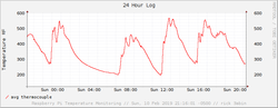
Here is a dashboard on IO.Adafruit.com:

The "placeholder for stack" is a copy of the stovetop temp. One of these days, I'll add the Stack thermocouple and update the dashboard.
The top 'gauges' update in realtime as new readings are received. The upper graph shows Stovetop and Catalyst temperatures in the last hour and the bottom graph shows the same over the last 24hrs.
Above, you can see my first fire of the season buring a few odds and ends around 4PM today, which lasted about 4 hours when I reloaded. I added more wood on the reload and kept the thermostatic air control a little higher about an hour before that screenshot (you can see the jump to ~1000F when the cat relit and it started cruising).
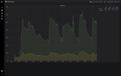
Here is the same dashboard viewed on my phone, which works from my home wifi as well as when I'm on the road for work and want to check in on how the stove is burning.

I wanted a display where I could see the results from the livingroom, so I build a display in a cheap wood pictureframe using some ~0.6" LED segment 4-digit displays.


This sits on top a rolltop desk and can be seen from the livingroom, dining room, and kitchen due to my open floor plan.
It works by using another ESP8266 chip to connect to my home wifi and then connecting to my account on IO.Adafruit.com. When the sensor/sender unit uploads a new reading (every ~8 seconds), it gets pushed to the display unit and the values on the LEDs get updated. This is probably about another $25-30 in parts in 1-off Amazon order quantities.
The great thing about the 'display unit' is that as long as it has an internet connection, since the datafeed is on the 'cloud', it can be in my living room, my office across town, or anywhere else in the world with an internet connection.
I'm hesitant to share, as my code isn't streamlined or pretty and is basically just hacked and mashed up example code. But it works for me. And this setup is incredibly stable.
This is my first time doing any kind of 'microcontroller' based projects, and while a little intimidating to jump into, its all pretty straightforward. One thing I've learned is that there are dozens of ways to do any part of this and another way could be a better fit for your needs. But this one is working well for me.
If there is interest, I'll post more details, parts lists, and pros and cons of the setup vs some alternatives, and some next steps I'm considering.
If you made it this far, thanks for reading and I'd love to hear from others who have done anything similar or are looking to!
Ryan
Long time reader and first time poster. Going onto year 5 with my BK Ashford 30 which I purchased thanks to great info on here. And I've become a much better woodburner thanks to all i've learned here.
In my effort to get better at using my stove, I'd been looking for temperature monitoring options. Not finding any that really fit what I wanted, I decided to see what I could build.
Here is the 'business end' of it sitting on a bench near the stove. This has been on a breadboard for 3+ years and is waiting for me to add the 3rd thermocouple (for the stack) and put it into a better enclosure. It has stainless sheathed wires to a thermocouple on the stovetop under the Ashford's convection deck and another thermocouple in the catalyst probe hole used by the original BK cat thermometer.
The brains of it is a NodeMCU ESP8266. The 8266 is basically a microcontroller with wifi capability and variety of input-output pins. It can be programmed using the Arduino IDE over a USB connection from your computer.
The sensors are K-Type thermocouples read by MAX6675 chips. These MAX6675's talk directly with the ESP8266 and there are existing libraries to make the coding easy. In 1-off quanties off Amazon (NOT the cheapest way to get parts!), the ESP8266 and the 3 thermocouples and MAX6675s will set you back around $30.
In operation, it starts up and connects to my home wifi accesspoint, and then about every 8 seconds, the NodeMCU takes a reading and posts it to IO.Adafruit.com. This is webservice that allows datafeeds, achives the results, provides a way to make dashboards viewable from a computer, tablet, or smartphone.
Here is a dashboard on IO.Adafruit.com:
The "placeholder for stack" is a copy of the stovetop temp. One of these days, I'll add the Stack thermocouple and update the dashboard.
The top 'gauges' update in realtime as new readings are received. The upper graph shows Stovetop and Catalyst temperatures in the last hour and the bottom graph shows the same over the last 24hrs.
Above, you can see my first fire of the season buring a few odds and ends around 4PM today, which lasted about 4 hours when I reloaded. I added more wood on the reload and kept the thermostatic air control a little higher about an hour before that screenshot (you can see the jump to ~1000F when the cat relit and it started cruising).
Here is the same dashboard viewed on my phone, which works from my home wifi as well as when I'm on the road for work and want to check in on how the stove is burning.
I wanted a display where I could see the results from the livingroom, so I build a display in a cheap wood pictureframe using some ~0.6" LED segment 4-digit displays.
This sits on top a rolltop desk and can be seen from the livingroom, dining room, and kitchen due to my open floor plan.
It works by using another ESP8266 chip to connect to my home wifi and then connecting to my account on IO.Adafruit.com. When the sensor/sender unit uploads a new reading (every ~8 seconds), it gets pushed to the display unit and the values on the LEDs get updated. This is probably about another $25-30 in parts in 1-off Amazon order quantities.
The great thing about the 'display unit' is that as long as it has an internet connection, since the datafeed is on the 'cloud', it can be in my living room, my office across town, or anywhere else in the world with an internet connection.
I'm hesitant to share, as my code isn't streamlined or pretty and is basically just hacked and mashed up example code. But it works for me. And this setup is incredibly stable.
This is my first time doing any kind of 'microcontroller' based projects, and while a little intimidating to jump into, its all pretty straightforward. One thing I've learned is that there are dozens of ways to do any part of this and another way could be a better fit for your needs. But this one is working well for me.
If there is interest, I'll post more details, parts lists, and pros and cons of the setup vs some alternatives, and some next steps I'm considering.
If you made it this far, thanks for reading and I'd love to hear from others who have done anything similar or are looking to!
Ryan