Boiler and Storage Design

  • Active since 1995, Hearth.com is THE place on the internet for free information and advice about wood stoves, pellet stoves and other energy saving equipment.

    We strive to provide opinions, articles, discussions and history related to Hearth Products and in a more general sense, energy issues.

    We promote the EFFICIENT, RESPONSIBLE, CLEAN and SAFE use of all fuels, whether renewable or fossil.

Aranyic

Burning Hunk
Sep 3, 2015
130
Ohio
I've planning to do a heating rework at my house and I really want to tie it into my central HVAC phelum. I've had a thread going here where I started processing my options. I really think I've settled on a Vedolux 37 and storage; it was pretty much down to this or a Heatmaster G series. In the end I decided that over the long haul I really feel I'll burn less wood using the batch burning and storage style and not having the idle time when the system doesn't call for heat.

I am leaning towards putting it in my basement which limits my storage options. I'm still working on storage tank pricing and specs.

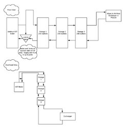
My current direction is the Vedolux V37 with 3 x 240 gallons ASME tanks. I've got a rough layout and I've got a few questions that I'm starting starting to get into on design.

  1. First question is on pumps. It seems like the LK810 is pretty universally liked as a mixing valve going into the boiler. Do the boilers have no circulation pumps on their own? Or would this replace an internal one? Then that pump would only be in use while the boiler is running and I would need a second circulation pump after the tanks between the water to air heat exchanger in the phelum? That would be the circulator that would be called when the thermostat calls for heat?
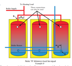
  2. Second is on the plumbing. I to use the 4 port tank model and run all of them in parallel one right into the other. I would have 1 1/4" coming into the first tank and probably 1" coming out of the last to the load. The biggest size I can do and keep everything uniform between the tanks is 1 1/2"; I figure go as large as I can there to promote water movement there? Or stick to something more uniform to the inlet or outlet?
I know I'll have more as I work through the design but that's where I'm at now. I have a rough drawing below. The boiler will be on an outside wall where the chimney can be run up past the peak of the house without sticking way above the roof line. The stairs are in the middle of the room. The 3 tanks will be lined up along the stairs; so the outlet/return from the boiler will go immediately up and over about 10' to the storage tanks. Then between the outlet from storage to the exchanger it would go up again and run along the joists.
 

Attachments

  • V37 Layout rev1.pdf
    11.7 KB · Views: 215
The LK810 is a mixing valve & circulator in one. It works very good. It is only circulating when the boiler is making heat, that is its only job - move heat from the boiler. Boiler does not come with a circulator.

Your heat loads would use another separate circulator. Its only job is to move heat to the load, in your case the plenum HX.

Your diagram has at least a couple fundamental things that should be changed. Can you post up a jpg of it?
 
Attached is a JPEG.

There's lots of valves I have not put in yet; ball valves and unions between each tank, air purge valves, etc. My initial idea was to use the below model but run 3 tanks in parallel:

upload_2019-2-5_8-25-8.png


Am I going to be significantly better off doing below (with adding the mixing valve on the return instead of the circulation on the output from the boiler)?
upload_2019-2-5_8-26-9.png


I'm hoping to avoid the design where I've got to do pipe stepping on all the different tanks unless it's really the best way to do it.
 

Attachments

  • V37 Layout rev1.jpeg
    V37 Layout rev1.jpeg
    44.2 KB · Views: 139
Ok thanks that's similar to what Tarm has on their boiler guide. Is the stepping of the header pipe sizes as you move along that run needed? It's mentioned in a NY hydronics paper that's linked in one of the sticks I've read through. I don't see much mention of it anywhere else. Though I think they are running one pair of headers/connections for the boiler side and a separate pair of headers/connections for the load side of the system.

Tarm Diagram:
upload_2019-2-5_12-24-33.png


NY Hydronics Diagram:
upload_2019-2-5_12-24-59.png
 

Attachments

  • upload_2019-2-5_12-21-27.png
    upload_2019-2-5_12-21-27.png
    35 KB · Views: 152
My lines are random thicknesses, fooling around with the program I did it in. No correlation to pipe sizing intended.

I could see where stepping sizes might improve things, or help ensure even flows, but I think most on here have just used all one size with very good results. Wouldn't hurt to do it while your at it.

Also the higher you can get your top ports & lower you can get your bottom ones will make the most of storage. And in your case, maximizing the size of your HX coil to the biggest you can get in your duct (oversize it) will help make the most of lower supply temps - also trying to make the most of your storage. You would typically need higher supply temps than say someone with cast iron rads or radiant lower temp emitters.

You will also need to design in overheat protection while at this. Ideally you would use very big piping between boiler & storage with very little horizontal separation between them for good convective flow if the power goes out. Elevating storage as high as you can also helps with convection. But sounds like you are a bit hamstrung with your space to not permit storage right next to the boiler. (There is a pic on the Smokeless site of storage tanks right next to boiler with 45° piping in between to promote convective flow). So you'll have to do what you can - dump zone likely being a primary consideration. I also use a big UPS on my LK810 when burning if I need to not be home when there is a fire going or if the weather is threatening a power outage.
 
Yeah I'll do a dump zone of some sort. It's an unfinished basement with poured concrete walls and floors. Currently it hangs out around 55 degrees in the winter with the pellet stove going upstairs and no HVAC running. I plan on walling in and insulating the storage to try and control heat loss from them. However in a power failure I should be able to dump heat pretty quick into a 1100sqft concrete basement with some used radiators or baseboards.

I've got a batter backup on my sump pump nearby that I maybe able to expand the battery capacity on and double dip there for unexpected outages. For longer outages we've got a generator inlet in place already.

Below are the tanks I'm currently looking at. I lose about 13" on the top and bottom of each tank but a decent amount of that is in the curved areas. They are the 240g from smokelessheat.com. I'm checking out some local suppliers also.

upload_2019-2-5_13-13-48.png
 
I used the stepped design on my headers 11/2 to first tank 11/4 to second, and reverse on the other side
And my storage is my heat dump
 
Yeah I'll do a dump zone of some sort. It's an unfinished basement with poured concrete walls and floors. Currently it hangs out around 55 degrees in the winter with the pellet stove going upstairs and no HVAC running. I plan on walling in and insulating the storage to try and control heat loss from them. However in a power failure I should be able to dump heat pretty quick into a 1100sqft concrete basement with some used radiators or baseboards.

I've got a batter backup on my sump pump nearby that I maybe able to expand the battery capacity on and double dip there for unexpected outages. For longer outages we've got a generator inlet in place already.

Below are the tanks I'm currently looking at. I lose about 13" on the top and bottom of each tank but a decent amount of that is in the curved areas. They are the 240g from smokelessheat.com. I'm checking out some local suppliers also.

View attachment 240277

Always fun looking back on the storage topic, once you've built a system...

You're gonna loose quite a bit of volume with those port locations on the 240 gallon ASME tank. My back of the envelope calculations come up with 177 gallons between the big ports on the sides. 0.25*pi*30*30*58/231.

I think storage is so important. Especially when you are planning on using a HX in your plenum which will require a higher supply water temperatures. Some rough calculations would be a good idea at this point in time. Something like... if I can charge two tanks to 180 degrees (or whatever), and I can use them down to 140 degrees (or whatever you come up with), then at my house's heat loss rate, how long am I going to be able to run on storage. As long as that time is acceptable to you, you're good to go...

Using those numbers, and again quite back of the envelope calculations here, I come up with about 176kBTU of usable storage. I could go back and look in my logs, but I'm typically cycling between 200kBTU and 250kBTU between single-load burns, with the caveat that I have a small house and a small heat load.

The biomass training sticky has updated content with some ASME tank manufacturers who are putting ports higher/lower and or using dip tubes or deflectors, etc.

maple1 gave you some really good advice and he has the boiler you are considering. I believe he has 660 gallons and wishes he had more! ;)
 
Thanks I'll take a look at that sticky for more tank options. Has anyone worked with the square tanks from New Horizon at all? I emailed them for a cut sheet to see what they look like.

Below is some figure I've settled in on my spreadsheet for heat loss and storage time. It's a hybrid of ideal scenario with some calculated inefficiencies. I realize I've got some more loss going on but it's my starting point that I'm at. Working on both a 50 and 70 degree water differential. No one would want to be near vents with 120 degree water running through the system but I _think_ it would still be putting heat into the house if you were looking at worst cases when it's -10 out at the end of the cycle.

 
Last edited:
Things will happen or be done that will skew precalced numbers.

When I am burning, I am recharging storage but also at the same time my loads are pulling off their biggest heat demand. I set back house temps a bit, and time the recovery from that to jive with when I am burning. I also heat my house a bit warmer than typical when burning, so the house itself acts a bit as storage. All to get the most mileage I can from my 660 gallons of storage. On paper, my storage would only be good for in the area of 9-10 hours of heat. But timing the burn to also line up with max heat demand and also heating the house a bit beyond setpoint gets me to going maybe 16-18 hours between fire out & fire re-lighting.

Also I see AS storage tank referenced. Maybe you will get some feedback from those who do it, but you might also get more mileage from pressurized storage than open storage when using a WAHX due to a few degrees of dT that might come into play using the extra HX needed for an open storage tank.
 
quick comments ...

The sticky also has some discussion on boiler and storage sizing. I find it will oversize your boiler from a BTU/hr rating point of view. But there is absolutely nothing wrong with the math, it's the conditions.

Second, I don't think you can count on 126850 BTU/ cubic foot of firewood. If that number were realistic, I could get 625kBTU into my 5 cubic foot firebox. And I can tell you that I cannot get that much wood into the firebox, because even at 70% efficiency, I would be transferring 437kBTU into my tank.

The sticky discussion uses firebox dimensions and some "packing density" factor which leads to how many lbs you can get into a firebox. From the number of lbs you can get into your firebox, you can use efficiency and the moisture content to guess how many BTUs in that firebox can be transferred to storage.
 
Yeah my recharge numbers are too optimistic. In some emails with Dean from smokeless heat he said as a general rule of thumb the average installation can recharge 500 gallons from a full firebox of wood. I'm not sure what degree range or anything they are working with but it's ballpark about 15% lower i think.

If I took the optimum 184,375 btu/cubic ft of ash and knocked off 20% for moisture in the wood; then assumed 70% from there for final efficiency (the furnace states 86%) then I've got piping loss, etc. That would put about 103 btu/cubic ft btu going into the tanks on the lower end? I'm hopeful that's a worst case and I'm somewhere in the middle realistically.

I'm heating 2400sqft plus basement (1400sqft uninsulated, has a couple vents there but I'm not looking to heat it really). Footprint is about 1400 sqft with 1000 sqft second floor give or take. I'll dig through the stickies again for that info. Is that all in the fine tuning biomass thread?
 
Yup. That's my capacity, I use every bit of it, and would love to have 1000.
And i am thinking of going to two thousand gallon storage from my one thousand
 
  • Like
Reactions: maple1
Always fun looking back on the storage topic, once you've built a system...

You're gonna loose quite a bit of volume with those port locations on the 240 gallon ASME tank. My back of the envelope calculations come up with 177 gallons between the big ports on the sides. 0.25*pi*30*30*58/231.

I think storage is so important. Especially when you are planning on using a HX in your plenum which will require a higher supply water temperatures. Some rough calculations would be a good idea at this point in time. Something like... if I can charge two tanks to 180 degrees (or whatever), and I can use them down to 140 degrees (or whatever you come up with), then at my house's heat loss rate, how long am I going to be able to run on storage. As long as that time is acceptable to you, you're good to go...

Using those numbers, and again quite back of the envelope calculations here, I come up with about 176kBTU of usable storage. I could go back and look in my logs, but I'm typically cycling between 200kBTU and 250kBTU between single-load burns, with the caveat that I have a small house and a small heat load.

The biomass training sticky has updated content with some ASME tank manufacturers who are putting ports higher/lower and or using dip tubes or deflectors, etc.

maple1 gave you some really good advice and he has the boiler you are considering. I believe he has 660 gallons and wishes he had more! ;)

I was looking through some of the stickies and have not found alternate tanks yet. I did however find someone that took a copper pipe and cut openings in it to act as a diffuser hanging into the top of a tank. In theory could I do the same thing with piece of iron pipe going into the side of a tank?

What I'd envision is using the 2x 2" ports.

Take a 2" nipple of some sort and run a 1.5" x 12" or similar pipe through it and weld the pipes in place. Weld the end of it closed (or with a small hole) and put 9-10 1/2" holes in the top or bottom depending on which direction I want the water to go. I figure a 1.5" pipe has a surface area of about 1139mm and an 1/2" hole would have a surface area of about 126mm. 9 would be an exact match for surface area.

Water would go into the tank and be diverted up or down depending on which direction the pipe was? I'm also debating if I could fit a 1 1/4" street elbow or something through a 2" hole to try something like that to actually divert the entire flow of water? Or would it still mix more than I want.
 
IMO I don't think straight diverter pipes will help a whole lot when drawing from storage. Unless you can elbow up or down inside the tank to actually put the inlet/outlet at top or bottom.
 
OK let's try one more theory. I may try it out and see if I can make it work. I will probably use copper inside the tank to not have near as much weight hanging off the 2" port.

Start with a piece of 10-11" pipe and over thread the end so I have about 2" of thread on it. Thread it through a brass bushing (2" > 1.25" hopefully) and have 8-9" of pipe inside the tank and 1" sticking out or so to tie the rest of my plumbing into.

Inside the tank do a 45 degree angle, 4" of copper and another 45 degree angle. Add about 5" vertical at that point and put a T on the end of it to direct the flow horizontally out both sides. If I need to cut some edges off the T in order to fit it through the 2" port on the tank then that's fine. In the example below (not finished) I used 1" galvanized because it's what I had handy to test if my 45's and pipe could fit through a 2: threaded union and it made it fine. The tank is a cylinder with a 15" radius so as long as I'm getting to the middle of the tank and no more than 11-12" then I should be able to spin the entire thing freely in the tank. I don't have the last nipple or T on the example.

The fittings and everything are so much thinner on copper I think I can go to 1.25" and match the piping from the boiler. I would use black pipe for the first few feet from the boiler. Maybe even overhead and until I get to the tanks before I transition.

internal cut.jpeg Internal Pipe.jpg

Now I've never threaded pipe before. Do they have a limiter on the cheaper pipe threaders or can you go as far as you want?

With the galvanized my entire thing would weigh in around 3.5# hanging off the pipe. I think copper would at least cut that in half. If I need to drill a hole or two right before the T in order to add some additional surface area to exit and not increase pressure I can.
 
I think, depending on your flow rates, you may be inducing mixing by spraying into the top of the tank. Why not just get a hole cut and a proper fitting welded on at the top of the tank?
 
  • Like
Reactions: salecker