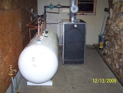
Fittings for my propane tank?

  • Active since 1995, Hearth.com is THE place on the internet for free information and advice about wood stoves, pellet stoves and other energy saving equipment.

    We strive to provide opinions, articles, discussions and history related to Hearth Products and in a more general sense, energy issues.

    We promote the EFFICIENT, RESPONSIBLE, CLEAN and SAFE use of all fuels, whether renewable or fossil.
Status
Not open for further replies.

goosegunner

Minister of Fire
Oct 15, 2009
1,469
WI
I found a used 1000 gallon propane tank. It was removed from service because the data tag came off.

The guy that I am buying it from said his dad is a qualified welder that can add what ever ports I need before I pick it up. $50 dollars and hour plus fitting cost.

The tank has fittings of

1-1/2" with dip tube
2"
plus two 1-1/2"

He said they are close together in the middle.

What should I have him add for ports?

It will be pressure tested before I pick it up. What psi should I tell them to go to?

gg
 
If you can stand the tank vertically and are willing to add up to six new taps I would be inclined to use the tank as a large hydraulic separator (HS). To do this you will need two large fittings (1-1/2") near the top that are directly across from each other, and two more near the bottom, again directly across from each other. At the top of the tank on the end of the bell you will need a small fitting for air removal. On the bottom install a fitting for a drain that can catch and remove dirt/debris. This setup will make the piping less complicated and should eliminate a circulator or two, an expensive air separator, and a strainer.

You will need a circulator on the boiler that will flow to the higher fitting on the tank (HS). Your zones (loads) will pick up on the opposite side of the tank (HS) and pull hot water when they call for heat. If you have more than one or two zones you may wish to install a manifold. Each zone will have it's own circulator. The zones will return the water to the tank (HS) on the same side as it pulled from. The boiler return will be opposite from the zone return. If the boiler is running with no loads calling for heat it will head back towards the boiler and continue to automatically charge the tank until a zone calls for heat. When a zone circulator starts it will pull off what it needs whether it is less, equal, or more than the boiler circulator is providing. If less some boiler water will return to boiler for continued charging. If the zone demand and boiler output equal it balances (rare in real world I suspect). And if the zone or zones demand is more it mixes some of the zone return (tank water) with what it being provided by the boiler. Finally if the boiler is off the zones will pull heat out of the tank(HS) and return it to the tank without any flow through the boiler.

For more information with pictures and diagrams of what I tried to describe Google "Bell & Gossett primary secondary header". There is a very informative pdf. file titled B&G primary secondary header on the BlueRidge company website.

I'm no expert by a long ways so take my advice with a grain of salt.

Hopefully other will chime in as well.
 
white pine said:
If you can stand the tank vertically and are willing to add up to six new taps I would be inclined to use the tank as a large hydraulic separator (HS). To do this you will need two large fittings (1-1/2") near the top that are directly across from each other, and two more near the bottom, again directly across from each other. At the top of the tank on the end of the bell you will need a small fitting for air removal. On the bottom install a fitting for a drain that can catch and remove dirt/debris. This setup will make the piping less complicated and should eliminate a circulator or two, an expensive air separator, and a strainer.

You will need a circulator on the boiler that will flow to the higher fitting on the tank (HS). Your zones (loads) will pick up on the opposite side of the tank (HS) and pull hot water when they call for heat. If you have more than one or two zones you may wish to install a manifold. Each zone will have it's own circulator. The zones will return the water to the tank (HS) on the same side as it pulled from. The boiler return will be opposite from the zone return. If the boiler is running with no loads calling for heat it will head back towards the boiler and continue to automatically charge the tank until a zone calls for heat. When a zone circulator starts it will pull off what it needs whether it is less, equal, or more than the boiler circulator is providing. If less some boiler water will return to boiler for continued charging. If the zone demand and boiler output equal it balances (rare in real world I suspect). And if the zone or zones demand is more it mixes some of the zone return (tank water) with what it being provided by the boiler. Finally if the boiler is off the zones will pull heat out of the tank(HS) and return it to the tank without any flow through the boiler.

For more information with pictures and diagrams of what I tried to describe Google "Bell & Gossett primary secondary header". There is a very informative pdf. file titled B&G primary secondary header on the BlueRidge company website.

I'm no expert by a long ways so take my advice with a grain of salt.

Hopefully other will chime in as well.

I'm not sure I agree with this assessment of "tank plumbing". It sounds much more complicated than it needs to be with "multiple connections" that may not be required? Traditionally you will put the hot water (boiler supply) in the top of the tank and also draw your heat zone supply from the same. Zone return and boiler return will both be the bottom of your tank (dip tube or fitting on the bottom).

For a good diagram see "simplest pressurized solution" sticky in the boiler room main page. It's really quite simple. I have my tanks plumbed with 1 supply and 1 return per tank. My zone supplies connect directly between the boiler and the tanks with a manifold. It's a very simple arrangment. Your Danfoss valve will prevent short circuiting through your boiler when it cools off...
 
I have:

Wood Boiler Feed & Return = 2
Load (House zone circulators) Feed & Return = 2
Relief Valve = 1
Tridicator = 1
Possibly An Aquastat = 1

So that comes to 7 total. I also put one 1-1/2" fitting in the bottom for a boiler drain in case I ever need to drain the tank.
 

Attachments

  • Boiler with Tank 001 small.jpg
    Boiler with Tank 001 small.jpg
    111.1 KB · Views: 1,274
goosegunner said:
It will be pressure tested before I pick it up. What psi should I tell them to go to?

gg

I filled my tank 95% full with water then put 80 psi air in the top and left it over night. Max working pressure should be 30 psi so I recommend 60 psi for a safety factor of 2 but others on here may disagree.
 
It's much easier to plug an un-used tap, then add one later! Add enough ports while you can.

Look it over good, typically there is a drain port at the bottom somewhere. On my tank this was a 1" so I put a Tee, increased it to 1-1/4" there and use it for a drain and my boiler return connection.

Along the top are several connections. Often one of those has a dip tube to the bottom. You want to be able to "leverage the whole tank capacity. I would try to have a 1-1/2" FIP on both ends top and bottom. Generally there are enough top connection points already for gauges, pressure and temperature, a pressure relief valve (very important) and a sensor well

Install a 30 lb pressure only relief valve, unless the boiler requires a lower pressure, relief, with a BTU rating in excess of the boiler output, 790,000BTU/hr. is a common size relief valve found at most supply houses. Pipe the relief line to the floor. It's not a bad idea to have a relief valve on the boiler, (usually code required) and one on the tank should they ever get valved off from one another.

One port can serve multiple functions. Return connection to the boiler at the bottom could also be a solar collector array return connection, so keep them 1-1/2". Both solar and wood want to see the coolest fluid temperature for max. efficiency.

hr
 
Piping storage as a hydraulic separator is very similar to the "simplest" method from a hydronics perspective. The bottom line is that both work quite nicely, and your decision to pipe one way or the other will probably depend more on space requirements, etc. Both methods use the same number of pumps... and both methods are equally as "simple." I am a huge fan of storage as a hyrdo-separator... it's just elegant... that having been said, my own system more closely resembles the "simplest" method.

As was mentioned before, a 1000 gallon tank is probably too tall for most people to install as a hydro-sep anyways.

A 1000 gallon horizontal tank should receive supply near the top of the tank, and send return water from the bottom when being charged. Upon discharge, the flow must be reversed so that the zones pull from the top of the tanks and return to the bottom. I recommend installing your own supply and return fittings so that they are as far apart from each other as possible. It's also helpful to use large diameter pipe to enter the tank as this will keep velocities down and reduce mixing of the stratified water. A horizontal tank doesn't stratify all that great to begin with, but they will stratify to some extent... so do what you can to take advantage of whatever stratification you can achieve. Inside a large volume of water, it is common to get cross currents of hot water that can travel directly (more or less) from supply to return when charging... I have seen this on my own tanks as return to the boiler begins to rise before the bottom sensor on the tank registers a temperature change. This effect, while not terribly detrimental to overall performance, can be minimized with slower velocities at supply and return ports that are placed as far apart as possible.

cheers
 
Fittings going in tomorrow.

I am going to have him add four 2" fittings.

one on top and bottom both ends. I will be able to plug any unused ports.

gg
 
+1 on the 'tank as hydro separator'. As Piker says and white pine describes very well. If you are using zone valves instead of pumps on each zone, this set up would also allow you to take advantage of a Grundfos Alpha. Also as Piker says "elegant"
 
Tarm Sales Guy said:
+1 on the 'tank as hydro separator'. As Piker says and white pine describes very well. If you are using zone valves instead of pumps on each zone, this set up would also allow you to take advantage of a Grundfos Alpha. Also as Piker says "elegant"

Maybe it won't work the way I am thinking. I use pumps on my heat zones controlled by a Taco 4 zone panel.


My existing OWB setup has a Primary/ Secondary manifold setup in my garage with pumps not zone valves.

I was hoping to use the simple system that nofossil describes. Leaving it all in place, putting the boiler and storage in the outbuilding. I thought I could charge the tank with its own pump as pictured and let my current pump be used for the load side circulator.

My heating zones call for heat and a Taco 4 zone controller starts the secondary circ. I could set the primary circ to run only when a zone calls for heat or run 24/7 like my current setup.


gg
 
This is a great forum. Been lurking for a good while but am now ready to start my install. Two 500 gallon propane tanks stacked horizontally connected to a Biomass 40. If the two tanks are connected with say two or three vertical connections wouldn't the tanks still stratify like a vertical tank?
I had thought of running a single piece of pipe from one end to the other for both the supply and return and drilling it 180 degree the interior length and placing it so the discharge would be horizontal. My thought is this would allow the tanks to stratify but let the load pull more or less straight from the boiler and the return to the boiler do the same from the load return. Does this have any merit?
 
Status
Not open for further replies.