By Forum Member nofossil
Storage does not have to be complicated.
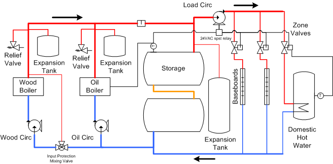
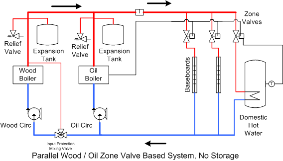
Ive chosen a simple parallel wood / oil system with zone valves as an example. At the bottom of this article there are links to plumbing and control wiring schematics for both before and after storage. The same basic approach would work with other system designs such as systems that use a circulator for each zone rather than a zone valve.
In this system, each boiler has a circulator that runs whenever that boiler is hot. Thats normal behavior - no changes are needed. These circulators need to have check valves to prevent reverse flow.
Each heating zone has a zone valve thats controlled by the zone thermostat (or aquastat in the case of the indirect DHW that Ive shown). This is also the normal configuration - no changes are necessary.
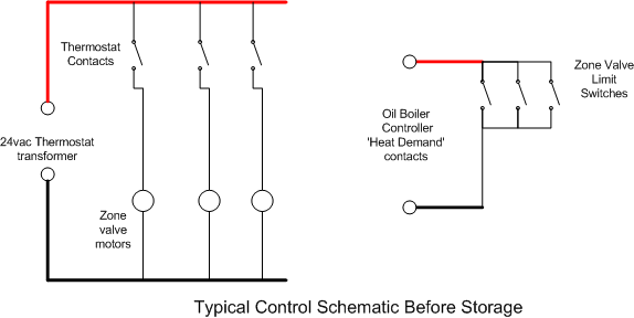
Zone valves have built-in limit switches that close when the zone valve is open. Normally those contacts are wired in parallel and connected to the oil boiler demand input. Here, we have to make some changes.
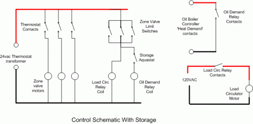
First, the zone valve limit switches are removed from the oil boiler demand input and connected to the 24vac thermostat transformer (see schematic).
Second, we need a 24VAC relay that we energize when any of the zone valve limit switches are closed. This relay will turn on the Load Circulator.
Third, we need a 24VAC relay for the oil boiler demand input - when this relay is energized, it creates a closed circuit that turns on the oil boiler. This takes the place of the zone valve limit switches.
Finally, we need an aquastat at the top of our storage with contacts that close only when the storage temperature drops below the minimum usable temperature - well say 140 degrees for this example. The signal from the zone valve limit switches passes through this aquastat before going to the oil boiler demand relay. In that way, if the storage is above 140, the oil boiler will not come on when the zones call for heat.
Theory of Operation
1) Heating from storage
If there is any heat demand, then the corresponding zone valve(s) are open and their limit switch(es) are closed. This energizes the Load Circulator. If the storage is above 140, and the wood boiler is cold, then the load circulator will draw hot water from the top of the storage and return cool water to the bottom of the storage. At this point, there is a clockwise loop from storage through the zones and back. There is no flow through either boiler.
2) Heating from Wood Boiler
If the wood boiler is fired up, then the wood circulator will come on. If theres still demand, then the load circulator is still running and the bulk of the flow will be from the wood boiler through the zones and back. Depending on the relative flow rates of the two circulators, there may be some flow into or out of storage.
3) Heating storage from the wood boiler
If the wood boiler is running and theres no demand, then the load circulator is off and there is no flow through the heating zones. In this case, the flow is from the wood boiler clockwise to the top of the storage and back from the bottom of the storage to the wood boiler.
4) Heating with oil
If theres demand from one or more zones and the storage is below 140, then the storage aquastat contacts are closed. This passes the zone demand signal to the oil boiler demand relay, which will turn on the oil boiler. At this point, the primary flow is from the oil boiler through the zones and back to the oil boiler. As in the case with the wood boiler, there may be some small amount of flow into or out of storage based on the difference in flow rates between the oil circulator and the load circulator. This should be minimal and not be a big concern.
With this approach, storage adds one circulator, one aquastat, and two relays. The system does exactly what you would want - heat from the wood boiler supplies zone demand first, and heats the storage whenever theres excess heat produced. Heat demands are satisfied by wood if its running, then by storage if its available, then by oil as a last resort. No additional controller is needed.
Components
There are no components that are particularly specialized. The relays, aquastat, and circulator can be obtained almost anywhere. If you have the time and inclination. eBay is a great source.
Any 24vac relay that can switch a couple of amps will work fine - Omrons LY2-AC24 (sold by Digi-Key as Z-788-ND) for example - theyre about $8 each, and you can get plug-in sockets for them that simplify connections.
The aquastat needs to be a break-on-rise model. For example, the Honeywell L6006A1145 would work well, and it has an adjustable differential temperature. Its about $80 from PexSupply and other sources. Installing a well for it is an exercise left to the reader.
The load circulator should be similar in size to the existing circulator(s), or smaller if the heat loads are much smaller than the output of the boiler.
I hope this helps. Comments, feedback, and improvements are welcome as always.
Other schematics:
1. Boiler installed basic diagram WITHOUT STORAGE
2. Control schematic WITHOUT STORAGE
3. Boiler installed basic diagram WITH STORAGE (same as graphic in mid-article)
4. Control schematic WITH STORAGE -