Hi Huff,
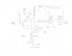
I've got wires jumping over each other all over the place in the diagram, but hopefully this helps. If this is on a 15A circuit use 14/3 and 14/2 cable. If it's on a 20A circuit then you have to use 12/3 and 12/2 cable. This diagram assumes that you have an always hot connection inside your controller/switching relay that you can connect the red conductor of the 14/3 cable to. In my Taco switching relay I can put two wires under each of the screw terminals, which I assume is okay. Otherwise, you would need to wire nut together the hot conductor coming into the controller with the the red outgoing conductor of the 14/3 cable and a black pigtail wire that connects to your controller's hot input.
Don't try jamming all of those conductors, wire nuts and the switch into a small 4x2 electrical box. In the U.S., for 14 gauge wire the box must be at least 16 cubic inches, for 12 gauge wire it must be at least 18 cubic inches, according to the NEC.
On the Leviton 3-way switches that I have used, the common screw is black and the two other conductor screws are gold. The black screw terminal is identified as being the "common" on the back of the switch.
You could do the same thing with a 3-way switch, but instead of the always hot conductor being carried on the red wire (of a 14/3 cable) from within the controller, the always hot conductor is just carried on a separate 14/2 cable. In that case you would have three 14/2 cables entering the switch box. The black from the controller goes to one of the gold screws of the switch, the black from the always hot conductor goes to the other gold screw, the black from the "common" (black) screw goes to the hot on the circulator, all of the white neutral wires are wire nutted together and all of the bare ground wires are wire nutted together, with a pigtail grounding the electrical box itself if it is steel.
Pete