Garn Install 15 mos. and winding down!

  • Active since 1995, Hearth.com is THE place on the internet for free information and advice about wood stoves, pellet stoves and other energy saving equipment.

    We strive to provide opinions, articles, discussions and history related to Hearth Products and in a more general sense, energy issues.

    We promote the EFFICIENT, RESPONSIBLE, CLEAN and SAFE use of all fuels, whether renewable or fossil.
Status
Not open for further replies.
rvtgr8 said:
Jim,

You are right on so many levels. The corrected drawing (which also may be flawed) is included in this post. The boiler side has my Taco 007-5f. The thing that I did not include in my rushed drawing was the fact that there is a HX at the tub. No fluids will co-mingle with my Garn. Unless there is a significant heat loss associated with the constant sharing between the two systems I am okay with it. My logic may be flawed here though. If the propane boiler is always on and the Garn is not, it seems to me it would burn all the time because it would be losing heat back to the Garn through the HX. But my intention is to use the Garn nearly 100% of the time. Am I way off base?

I understand you redid some of your system...was it anything to do with this same situation? Is my drawing any clearer?
4043999749_409aaf4e56.jpg

What are you using to make the return of the house side of the system flow through the main HX?
 
Heaterman,

According to this drawing the answer to your question is simple...magic! But since magic is on backorder at Pex supply, it looks as though I need to add a circulator (Grundfos similar to HX pump on Garn side) to the legs of the closely spaced tee. I will add another couple drawings shortly. Thanks for looking.
 
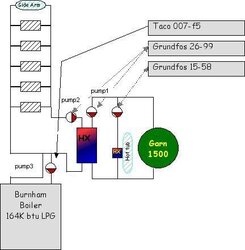
Hmmm... I think I like the earlier drawing a little better for our purposes. Let us start with the drawing you had in post #19, that I also quoted above....

In that drawing, I don't see ANY serious issues with the Garn side of the house HX... You could play with where the pumps are at, and how you have the hot tub plumbed in, but what you have drawn should work fine...

Where I saw issues is on the HOUSE side of the HX. As drawn in that picture, you would send all your circulation through the Burnham, and nothing through the HX, because you are tieing into the house loop with a pair of closely spaced tees, and don't have anything in the HX loop to make water flow through it.

For the purpose of this discussion, that entire ladder looking structure of the radiant flooring and sidearm exchanger could be considered as one big blob called "load" with two pipes coming out, supply and return... I don't see a need to change anything in the blob, but you need to do something to connect the HX and the Burnham to it, the question is what? The Burnham and HX can also be thought of as blobs that function as heat sources, with two pipes, one that gets cold water in, and the other hot water out.

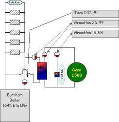
Now in the picture you just posted in #23, you have the HX drawn in differently, so that it is in the main loop along with the Burnham, so the water comes out of the pump, goes into the Burnahm, (I'm going to call it the BH after this...) out of the BH to the expansion tank and load supply (per the standard "pumping-away" guide this is wrong BTW, as the pump should be pushing AWAY from the ET, not towards it) through the load, into the HX, and from there back to the pump. This works, and would do the job, but you will be wasting a fair bit of energy keeping the BH hot, and pumping water through that added resistance when you don't have to. IF the Garn and the BH were both running at the same time, you would also be pulling heat out of the house loop and sending it to the Garn; but if the Garn pump was off, as it should be if the BH is on, you shouldn't have any flow on the Garn side of the HX, so you shouldn't lose a lot of heat there, but it puts extra pumping load on going through the HX when you don't need to.

I don't know which drawing reflects what you are actually doing, (I would note that the Garn side in the two drawings is also significantly different, but I am not going there in this post!), but since both drawings have problems, and either the fixes I'm proposing would solve both drawings, it doesn't matter...

Let me go over the two ideas again.... Draw them both out and see if they make sense to you, if either or both don't, post what you came up with so I can make sure that you are drawing what I'm describing...

#1 Is to convert the house side into a primary/secondary system, with the load as the primary loop, and the BH and HX as independent secondary loops. To do this, disconnect the BH, and tie the supply and return of the house load together, moving the existing pump to the other side of the expansion tank while you are at it. Put in two pairs of closely spaced tees as well. Connect the BH and a second pump w/ flow check in a loop to one of the pair of tees, and the HX and a third pump to the other. These two new pumps can both be pretty small, size them to provide adequate flow around a loop consisting only of the BH or HX, the two tees, and the connecting pipes. Set up the controls so that when you have a call for heat, the load circ and the circ for whichever heat source is being used comes on, with the unused circ staying off...

#2 Is to put the two loads in parallel, so that you only have one pump on the house side, and add control valves so that you only get flow through the heat source that is being used. To do this one, move the pump to the other side of the expansion tank so that it pumps away from the tank into the house load. Put a T on the supply and return sides of the house load, and connect the cold water in sides of the BH and HX to the return of the house load, and the hot out sides to the supply side. Your pump now sends water through the house load and then splits the flow with some going through the BH and some through the HX, then brings them back together at the expansion tank to go back to the pump. Now, in order to choose which heat source you use, either put one zone valve in each of the lines to the HX and BH, or an A/B selector valve at either of the tees. Set the controls up so that on a call for heat, the house load pump turns on, the zone valve for the source you want is open, and the other closed (or the selector is in the right position), and you turn on the appropriate heat source...

Does that help?

Gooserider
 
Now what are you guys doing posting stuff while I'm busy typing??? :cheese:

Your drawing in #27 approaches what I was suggesting in my #1 idea above, you just need to make the BH connection a pair of closely spaced tees, and move one of those two pumps off the HX loop and onto the house load loop... If you do that, you shouldn't need any extra valves, though it would probably be a good idea to put a flow check on the HX and BH pumps just to make sure you don't get any ghost flow... Edit - turn that BH pump around as well!

That help any?

Gooserider
 
I did a quick hack job with MS paint on your drawing. This may be the cheapest route, no zone/ebv required.
As goose points out there are soooooo many ways to do this......

pump 1 and 2 run when heating with garn, pump 2 and 3 run when heating with burnham
 

Attachments

  • 4045712318_5d34572500ka.jpg
    4045712318_5d34572500ka.jpg
    24.4 KB · Views: 595
kabbott said:
I did a quick hack job with MS paint on your drawing. This may be the cheapest route, no zone/ebv required.
As goose points out there are soooooo many ways to do this......

pump 1 and 2 run when heating with garn, pump 2 and 3 run when heating with burnham

That is another way to do it, and it would work, but you are still pumping through the HX when runing on the BH. Also you need to look at the pump flow directions, remember that you want counterflow through the HX...
 
another option, simple parallel circut only one pump needed when running burnham. flow checks are needed in both burnham pump and HE pump
 

Attachments

  • 4045712318_5d34572500ka1.jpg
    4045712318_5d34572500ka1.jpg
    23.8 KB · Views: 398
keep in mind this was a quick hack, I made no atempt to change pump dir etc.
 
kabbott said:
another option, simple parallel circut only one pump needed when running burnham. flow checks are needed in both burnham pump and HE pump

Very nice... A variant on what I was doing with my suggestion #2, except I was using zone valves and one pump on the house loop side. I think your approach is better Kabbott as it gets rid of the zone valves, and thus would work a bit simpler on the controls, just run the pump for the desired source and leave the other off.

Gooserider
 
A few things to keep in mind:
1. No heat to hot tub when heating with Burnham.
2. Your drawing shows a side arm for DHW. My concern with this is side arms(at least the one I have) take a long time to heat x amount of water
compared to an indirect tank with a coil inside. This means you will have 2 pumps running for a long time even when no house zones are calling for
heat. Prolly not very efficient for heating DHW.
I will let some of the heating pro's debate that one.

I suspect it is getting a little "chilly" out west esp at your elevation. I am sure you will love that beast when you get it in service.

Kris
 
Kabbot,

Hack away! I can do your drawing. Goose, what do you think, will this work with a modicum of efficiency? I read pumping away after I got conned into pulling water into the boiler rather than the other way around. The system works well, but I know it would work better if done as you suggest.
 
rvtgr8 said:
If this had proper valves, could this be a solution? Also, running back through the boiler is bad because it represents an additional loss of heat?

4045712318_5d34572500.jpg

Yes but you would need only one circ on the system side of the HX. You could also do it really simply by adding a ball valve inbetween your closely spaced tees going to/from the HX. When you want heat from the Garn simply close the valve which would divert system side flow through the HX and back through the Burnham. When You want to run the Burnham only in shoulder seasons simply leave the ball valve open and allow the flow to go directly to the gas boiler, bypassing the HX. Depending on the flow required in the system and the head added by the HX you may be able to get away with the circ you presently have on your system doing all that work. I think that I would at least try it that way unless you want to have some type of mechanical/electrical control doing the thinking for you.
 
rvtgr8 said:
Kabbot,

Hack away! I can do your drawing. Goose, what do you think, will this work with a modicum of efficiency? I read pumping away after I got conned into pulling water into the boiler rather than the other way around. The system works well, but I know it would work better if done as you suggest.

Not sure which idea you mean by "this" but I think any of either my ideas or Kabbots would work very nicely once tuned up a little. Heaterman's idea of putting a ball valve between the tees of your first drawing would work if you didn't want the automatic switchover between the two sources.

If you do want the switchover, I think Kabbot's idea in Post #32 is the simplest and neatest once you get the pump directions and such fixed properly.

Gooserider
 
Here is my latest drawing based on Goose and Kabbot's ideas. Is this a possible solution and does this provide for an option to use my Tekmar 356 to control the Burnham as a backup? Also, am I correct in my belief this corrects my "Pumping Away" problem?

4046948979_99efedf476_o.jpg
 
This looks better!
You should add where your expansion tank is located so we can give input on PONPC.(pumping away)
Also you still show both sides of heat exchanger flowing the same direction. Minor change, one side should flow the opposite direction.(counter flow)

House side 26-99 on heat exchanger needs flow check.

Kris
 
Couple things, the E/T should be on the other side of the burham pump. This will put PONPC at the inlet of both pumps.
Other thing is that the flow checks should be after the pumps I think( if there not built into pumps) That way they will not
restrict the inlet of the pumps.

Not familiar with your tekmar control but when the garn is to cool for heat you want to switch to the burham pump and turn on the
burner. Lots of ways to do that too.that may be a whole-nuther diagram :ahhh:

Lets see what heaterman and the others think.......
 
Yes :)
 
Yes, diagram in post #43 looks pretty good. Only change I might make is to put the ET on the line going into the BH in order to put the PONPC closer to the HX pump, but that is relatively minor - it might be worth asking the "guys that get paid for this stuff" about that... It might also be worth putting an air and / or dirt separator on the house loop some place that always gets flow - say on the red line between the lowest "L" Tee, and the Tee where the HX and BH come together.

The custom is usually to put a spirovent or equivalent at the junction with the ET, and that usually works well enough, but with this setup, the ET is only going to get actual flow past it when the BH is running... The other option might be to put the ET on the blue line between the "L" and HX tees - that way it would always see flow, and would work in terms of pumping away, but I don't know if it's the best for air separating...

Gooserider
 
Gooserider said:
Yes, diagram in post #43 looks pretty good. Only change I might make is to put the ET on the line going into the BH in order to put the PONPC closer to the HX pump, but that is relatively minor - it might be worth asking the "guys that get paid for this stuff" about that... It might also be worth putting an air and / or dirt separator on the house loop some place that always gets flow - say on the red line between the lowest "L" Tee, and the Tee where the HX and BH come together.

The custom is usually to put a spirovent or equivalent at the junction with the ET, and that usually works well enough, but with this setup, the ET is only going to get actual flow past it when the BH is running... The other option might be to put the ET on the blue line between the "L" and HX tees - that way it would always see flow, and would work in terms of pumping away, but I don't know if it's the best for air separating...

Gooserider

I thought about moving the E/T but when running the H/E pump there is no flow through the Burnham and therefore no pressure drop. If
it is already installed at the Burnham I would not worry about it. If you have to install/move it anyway then you could put it where Goose suggested.
 
rvtgr8 said:
Here is my latest drawing based on Goose and Kabbot's ideas. Is this a possible solution and does this provide for an option to use my Tekmar 356 to control the Burnham as a backup? Also, am I correct in my belief this corrects my "Pumping Away" problem?

4046948979_99efedf476_o.jpg

You will want to wire up the 99 feeding the HX to run only on a call for heat otherwise it will be deadheaded when all zone valves are closed in that piping arrangement. But otherwise, I'd run with that one if you add the air scoop/xpn tank right below the circ coming off your burnham........if possible.
 
Kris, Gooserider,

I want to thank you both for helping me with this. Hearth.com provides a remarkable service for so many people in difficult times. My wife and I moved out here from the Denver area twelve years ago. We are retired and on fixed incomes. We invested in the Garn to be able to remain out here only to find the installation cost was nearly as much as the WHS itself. We have no choice but to learn and do for ourselves. We aren't poor mind you, but being able to eliminate a gigantic propane bill is the difference between living in our dream home and not. I taught public school for 25 years and I never take education for granted. It means a lot when strangers, with expertise such as yours, reach out and share. Thanks again

Robert
 
Status
Not open for further replies.