
My igniter just burned out and I just got done installing a new one. After installation and plugging the unit in, I noticed the igniter turned red. The issue is my thermostat was turned all the way down and the igniter shouldn't be heating up. After watching the stove for a few cycles, I noticed that the igniter is not turning off at all. It is staying on, even when the auger and fans are off. Any ideas what the issue could be? Control board, something else? Thanks in advance. FYI it is a Lopi Yankee stove.
Igniter/Hot rod issue
- Thread starter mlambert40
- Start date
-
Active since 1995, Hearth.com is THE place on the internet for free information and advice about wood stoves, pellet stoves and other energy saving equipment.
We strive to provide opinions, articles, discussions and history related to Hearth Products and in a more general sense, energy issues.
We promote the EFFICIENT, RESPONSIBLE, CLEAN and SAFE use of all fuels, whether renewable or fossil.
You are using an out of date browser. It may not display this or other websites correctly.
You should upgrade or use an alternative browser.
You should upgrade or use an alternative browser.
heat seeker
Minister of Fire
If the ignitor is always on, it's most likely a shorted triac or relay on the control board. An inexpensive fix if you can solder on a circuit board.

If the ignitor is always on, it's most likely a shorted triac or relay on the control board. An inexpensive fix if you can solder on a circuit board.
Is it as easy as unsoldering the 2 or 3 joints, and replacing the triac/relay? Any tricks to soldering on a control board? I have done some soldering in my time, but that was years ago. Thanks for your time!
if you have a cracked track i found the easiest way is to go back to a good section and scrape coating of and solder a pc of wire on and then do the same on the other side of crack. May just be me but if iv tryed to solder a track at the crack it lifts off the board as im scraping the coating off. You can also solder a wire to a solder point on each side of crack if its easier.
Ssyko
Minister of Fire
Yes its that easy. Get the numbers off the old triac and order the same part. Mouser, digikey just to name a couple parts site. It’s easer to cut the triac off the board and then use a solder sucker and remove the remaining pins & solder. Try not to heat the board to much.Is it as easy as unsoldering the 2 or 3 joints, and replacing the triac/relay? Any tricks to soldering on a control board? I have done some soldering in my time, but that was years ago. Thanks for your time!
heat seeker
Minister of Fire
What Ssyko said.
Use a low wattage iron - 25 watts should be enough. Too much heat will lift the trace off the board. Use ROSIN core solder only, not acid core! Use anti-static protocol, some components are static sensitive. It's not hard to replace components on a board, it just takes a bit of finesse.
Use a low wattage iron - 25 watts should be enough. Too much heat will lift the trace off the board. Use ROSIN core solder only, not acid core! Use anti-static protocol, some components are static sensitive. It's not hard to replace components on a board, it just takes a bit of finesse.
Thanks for the help and and advice Ssysko and heat seeker. One more question if I may. I tried to find the matching part online and I'm getting mixed results. Here is the triac on my board. Any chance you could tell me which one I need? Thanks

I tried to find the matching part online and I'm getting mixed results. Here is the triac on my board. Any chance you could tell me which one I need? Thanks
Available at Digikey. $1.31
https://www.digikey.com/product-detail/en/littelfuse-inc/MAC228A6G/MAC228A6GOS-ND/918549
Are you absolutely sure that the igniter gets power from the triac on your pic ( and not from a relay as on the Whits ) If so, one of the terminals on the igniter plug should be connected to main terminal 2 ( MT2 ) on one of the triacs. Easy to test with an ohmmeter: MT2 is the center pin of the three and is also connected to the triac housing. So, one test probe to MT2 and the other to one of the terminals on the igniter plug. If you get a 0 Ohm reading on one of the igniter terminals, you have found the right triac.
I count 4 triacs on your pic: 3 with heat sinks and one without. On the newer touchpad control boards in the Whitfields there's only 3 triacs in all ( and all are MAC228-A6 ).
The igniter gets power from a relay on my Whitfield, so it makes sense that your Lopi has an extra triac for the igniter instead of a relay.
How many relays are present on your control board?
Triac pin ID for the MAC228:
View attachment 221466
Ssyko
Minister of Fire
Thanks for the help and and advice Ssysko and heat seeker. One more question if I may. I tried to find the matching part online and I'm getting mixed results. Here is the triac on my board. Any chance you could tell me which one I need? Thanks View attachment 221462
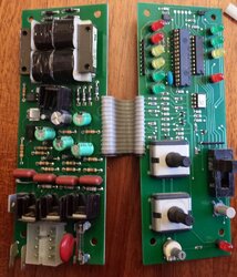
Could you give the make and model of the stove and a pic of the whole board?
Lopi Yankee is the make/model. 2003 I believe.Could you give the make and model of the stove and a pic of the whole board?
Nice sharp pics, thanks. We clearly see that there are no electromechanical relays on the boards, so the igniter has to be powered by one of the four triacs. We just need to find out which one.
This diagram should be of a 2001 Lopi Yankee:

From the diagram we see that the igniter gets its hot phase from pin #1 in the Molex plug, so with an ohmmeter you can easily find which triac that has its MT2 connected to pin #1:
The way I read your pic, pin #1 in the Molex is the upper one to the right, so with one ohmmeter probe on pin #1, start touching the metal part of the triac housings one at a time with the other probe, until you get a 0 Ohm reading. There you have the igniter triac.
It is also possible to find it visually, simply by following the copper trace connected to pin #1. To which MT2 does it lead?
One thing is making me scratch my head, when comparing this Lopi control board to those in the newer Whits: How does the start up procedure work on a Lopi stove? On the Whits a bypass relay is energized during the warm time ( 30 minutes ). I don't see any relays like those on the Whitfield controls. Unless, there actually is a solid state relay hiding somewhere on the Lopi board. mlambert40, can you read the text on the two black components on the leftmost board? They are mounted horisontally on the leftmost side of this board, close to the transformer.
This diagram should be of a 2001 Lopi Yankee:
From the diagram we see that the igniter gets its hot phase from pin #1 in the Molex plug, so with an ohmmeter you can easily find which triac that has its MT2 connected to pin #1:
The way I read your pic, pin #1 in the Molex is the upper one to the right, so with one ohmmeter probe on pin #1, start touching the metal part of the triac housings one at a time with the other probe, until you get a 0 Ohm reading. There you have the igniter triac.
It is also possible to find it visually, simply by following the copper trace connected to pin #1. To which MT2 does it lead?
One thing is making me scratch my head, when comparing this Lopi control board to those in the newer Whits: How does the start up procedure work on a Lopi stove? On the Whits a bypass relay is energized during the warm time ( 30 minutes ). I don't see any relays like those on the Whitfield controls. Unless, there actually is a solid state relay hiding somewhere on the Lopi board. mlambert40, can you read the text on the two black components on the leftmost board? They are mounted horisontally on the leftmost side of this board, close to the transformer.
Last edited:
Thank you VERY VERY much for all of your help and info I have attached a pic to make sure I am getting you the part numbers of the correct components you are requesting. Please let me know if these are the correct 2.

I have attached a pic to make sure I am getting you the part numbers of the correct components you are requesting. Please let me know if these are the correct 2. Ssyko
Minister of Fire
Haha. As you can probably tell, I have NO IDEA what I am doing. The last thing I am going to do is start cuttingYes that is the correct 2. Don’t do any cutting till we figure out which triac is the culprit")
")
Ssyko
Minister of Fire
Ssyko
Minister of Fire
Ssyko
Minister of Fire
Mlambert if you have a multi meter you can ck the pin 1 to the MT2 of the triac and make sure my assumption is correct
For stovensen's review
Well spotted, Ssyko

Mlambert if you have a multi meter you can ck the pin 1 to the MT2 of the triac and make sure my assumption is correct
It is absolutely certain that the copper trace from pin #1 on the Molex leads to MT2 on the triac, you pointed out on your drawing.
The heat sink on the triac appears to be similar to those in my Whitfield and here its possible to read the text on the triac. All triacs on my board are the MAC228-A6. My guess is that all four on your board are also this type, but you have to be sure, before ordering.
I suggest you order at least a handful of triacs, while you're at it. Triacs may fail suddenly and without any warning, as we know now.
Now comes the real challenging part: Unsoldering the triac and heat sink without damaging the copper traces. We can see that the heat sink is soldered to a pad just below the MT2 pad.
Mlambert40, I hope you have soldering tools and the skill to do this, otherwise you may have to consult some electronics enthusiasts ( geeks
) in your circles to do the job. Geeks usually love technical challenges.
Last edited:
heat seeker
Minister of Fire
I don't see the triacs very clearly, but from what I can determine:
If you can cut the triac leads with the heat sink in place, I'd do so, then unsolder the sink, install the new triac, then the sink.
The heat sinks don't appear to be fastened to the triacs, just use a bit of springiness to make physical contact. They appear to be held to the board at one point. I would remove the heat sink first by heating that point and pulling the sink away with pliers (if you can't do the above).
Then I would cut the triac leads to remove the triac, the unsolder the bits left on the board. This would reduce the amount and time of heat to a minimum, reducing damage to the traces. Installation would simply be the reverse.
Use some heat sink compound between the triac and the heat sink. It is important to make sure the triac is properly cooled by the heat sink.
I wish you lived near me - I love to do this kind of work.
Ssyko
Minister of Fire
Before any components get removed. Lets test the triac and be sure it has failed.
Attach the negative meter lead to T1 and the positive lead to T2.
5) Now, using a screwdriver blade, create a momentary short between T2 and the gate. This brief contact should turn the triac "on", thus producing a meter reading of about 15 to 70 Ohms.
6) Next, disconnect one of the meter leads, then re-connect it. The meter should return a reading of infinity.
7) And finally, reverse the meter leads and repeat the tests. The results should be the same.
A shorted/melted triac will indicate zero Ohm betweenMT1 and MT2 no matter what's happening on the gate
Last edited:
Thank you all VERY VERY much for your help, you guys have been incredibly helpful. I am going to take my board to a guy here local that works on control boards as this is very much out of my wheelhouse. I have passed him the link to this thread to aid him with the repair. I will post back to this thread once the work is complete and hopefully everything is resolved. Again, Thank you very much
Similar threads
- Replies
- 7
- Views
- 1K
- Replies
- 7
- Views
- 1K
- Replies
- 5
- Views
- 347
- Replies
- 2
- Views
- 369