OMG it looks sooooo Industrial.

  • Active since 1995, Hearth.com is THE place on the internet for free information and advice about wood stoves, pellet stoves and other energy saving equipment.

    We strive to provide opinions, articles, discussions and history related to Hearth Products and in a more general sense, energy issues.

    We promote the EFFICIENT, RESPONSIBLE, CLEAN and SAFE use of all fuels, whether renewable or fossil.
Status
Not open for further replies.
That is likely a resistor


Get the numbers and such off the thing, and you can likely get a new one at the local electronics shop

Without looking real carefully at the schematic for the board, I can't say for sure about using a pot on each resistor.

Replace the broken resistor and give it a whirl.

Snowy
 
gotta disagree on that one . that's an electrolytic capacitor . get the numbers off it and head down to radio shack . if they don't have it , just order one from digikey or mouser . the shipping will probably be 5 times the cost of the cap but .....
 
I was looking at the wrong part then.

Yesssss, the shack may have it, if you are close to a Fry's they may have it.
 
I will look and see if I can find some numbers on it. I never have had luck soldering on circuit boards. Don't have much to lose though.
 
I will look and see if I can find some numbers on it. I never have had luck soldering on circuit boards.

An electrolytic capacitor is a polarized component, so before unsoldering it, take exact notice of how it is placed on the pcb. See photo below. To find the correct replacement, these values must be correct: Maximum voltage rating and capacitance value. The polarity is usually marked with a white band indicating the minus terminal as shown on the pic.
Note: Capacitance value and polarity are critical, but if your electronics shop doesn't have a replacement with the same maximum voltage rating, then they will have one with a higher rating. Example: The cap on the pic has a max. voltage of 25 Volts. This can be replaced with one of a higher voltage, in this case: 50 Volts. But ONLY with one of a higher voltage rating, NEVER with one of a lower. Capacitors CAN explode if their max. voltage rating is too low. Now you have been warned to take care with this.
electrolyticcapittre.jpg
Now, as for improving your soldering skills... on Youtube there are many very useful tutorials. This is one of the best I could find so far, since it covers most of the challenges you'll face, when starting to solder. Enjoy:cool:

 
Last edited:
  • Like
Reactions: rafmt and Bioburner
Great info on the capacitors.

The soldering tutorials are helpful.

If you don't feel real comfy, go to Radio Shack and get a little project board and some tiny wire, then practice some on the board before working on the stove.

I would also recommend flushing the stove board off with an electronics spray cleaner to flush off the years of dust, cooking oils and whatever else has settled on the board (outdoor job)

Clean is the buzz word. If the board is dirty you could get a bad solder joint.

I just did the small circuit board thing for a resistor array and "clean and careful" are the key words here.
Get the iron hot, tin it (Add a bit of solder) wipe it clean on a rag, then while grasping the component with a little bit of force, touch the hot irons tip to the solder spot and within a second the part will pull through.

KEY WORD HERE IS "GET ON IT, THEN OFF JUST AS SOON AS IT MELTS AND THE PART IS OUT"

Don't fry your board !!!

Good luck

Snowy
 
Thanks for the great info....I decided it is cheaper to let the electronics shop solder the $1.15 capacitor. If I would have tried, that piece would have cost me $300-$400. ( cost of a new board ) The electronics shop charged me $5.00. Took him about 3 minutes. Tomorrow I will plug it in the stove. See what happens.
 
Sweet

Keep us posted :)
 
Made some good strides this evening on the "Box"

The other day I scarfed up a cool little plastic case to house the resistor pack.
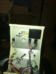
Carved a hole in the end for the wires and squirted in some black RTV to secure the PCB and snapped the cover back on.

A strip of double side tape and the "Widdle box" is all secure in the panel.

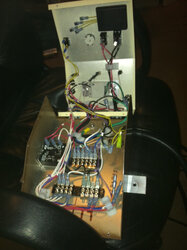
In the piccy you can see the back of the rotary switch with its tabs showing.
Just have to make up the 4 wires to solder to the 3 on top and the one directly below them (Common terminal)

A spade on each wire and connect the Low Med High to the 3 terminals on the resistor pack, then connect the common to the timer and also the common from the rotary switch to the timer.

Very minimal work left to get it completely tidy'd up in the new panel.

I found the little case at Fry's Electronics for a couple $$

I want to do another one of these units for the other stove, and add some mods that will be better suited to the larger stove.

A different resistor pack for a better feed/heat selection, and a control for the low temp snap switch cut off.
The Prodigy does not use a low temp cut off with a start timer, but rather an on/off switch.
The low temp switch simply allows the stove to be shut off and continue the draft fan until the thing is cooled off.

I prefer to shut off the fuel and keep the draft and room air blowers on til its cooled down, then shut it off.

The only down side is the lack of a fail safe in case of a misfire, but that's how they made the little baby Whit. :ZZZ

Always better the more times you do it. :)

Snowy
 

Attachments

  • panelfinished1.JPG
    panelfinished1.JPG
    54.9 KB · Views: 224
  • Resistorpack1.JPG
    Resistorpack1.JPG
    49.9 KB · Views: 193
Status
Not open for further replies.