Thank you and asking for help with schematic

  • Active since 1995, Hearth.com is THE place on the internet for free information and advice about wood stoves, pellet stoves and other energy saving equipment.

    We strive to provide opinions, articles, discussions and history related to Hearth Products and in a more general sense, energy issues.

    We promote the EFFICIENT, RESPONSIBLE, CLEAN and SAFE use of all fuels, whether renewable or fossil.
Status
Not open for further replies.

dswitham

Member
Hearth Supporter
Dec 27, 2009
62
western ME
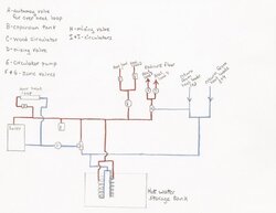
First, thank you all for the info that you post on here. It has been very informative. My husband and I have finally decided to replace our 30 year old tarm with a gasification boiler. We are getting a Biomass 80 that should be delivered in a week or two. We had planned on just pulling out the Tarm and replacing it with the Biomass, but realized that some things aren't plumbed right and the piping is too small for the new boiler. I have attached a basic schematic just as a starting point for what we have come up with for a piping layout. We have a friend that is a plumbing and heating guy but hasn't dealt with wood boilers that much so he can't help a lot with the design but can help with the install if needed. I haven't included in the design check valves or places to fill and drain the system or purge the air. I just wanted to get a basic idea first if what we were thinking was even on the right track. Pressurized storage is out and we have the materials to build a storage tank. This will be going in the basement as we already have some of the plumbing that won't be changed such as the radiant heat zones or how they are plumbed from the manifold out. (At least I hope not.) Any suggestions for a different way to do this would be appreciated or if there are any glaring errors that we don't know about. Thank you all.
Shelly
 

Attachments

  • SCAN0001.jpg
    SCAN0001.jpg
    35.7 KB · Views: 679
I don't have time to analyze it carefully, but it looks good. It's essentially the open storage version of the 'simplest pressurized storage' schematic that I posted a while back. I think you'll want to use 3 speed circs so that you can balance flow in the boiler / storage loop vs. flow in the storage / load loop. For instance, too much flow through the zones would result in lower zone water temps as you'd always be drawing some through the storage coils.
 
How does your overheat loop circulate? Thermosiphon? If not, you probably want to put the curculator (C) right next to the boiler return so you have positive circulation. I would then put the mixing valve (D) before the circulator with boiler supply coming in the "top". The overheat return would T in with the reast of the returns. A battery backup on the main circulator is a good idea. Mark at AHONA plumbed a secondary "emergency" circulator in his setup which is run by a relay and a UPS. Nice solution to a power failure problem. I have batteries and an inverter that I am going to use for my boiler power so that I will have significant backup power (at least enough for one complete burn).
 
Also, do you not need a mixing valve on heat loads 1 & 2? I don't know what these loads are but you could be putting some really hot water 180+ through those loops.
 
Are you using the same coils or separate coils for charge/ discharge and are you using any back-up heat source?

P.S just to say welcome to the group here and good luck with the project.

Henk.
 
First off, I would say that IMHO an emergency dump zone should ALWAYS be setup to thermosiphon - I wouldn't accept an emergency dump that relied on electrical power or other mechanical circulation... Looks like that is what the OP has in mind.

Otherwise things look good, except that I don't really see a way to reverse the flow direction when drawing from storage rather than charging from it... (i.e. the back to back circ trick or something in the way of a switching valve.)

I also don't see anything that would block flow through the boiler when it is cold? (perhaps one of the flow checks you said weren't drawn in yet?)

Definitely looks like a reasonable starting point at any rate...

Gooserider
 
Thank you all for the feedback.

We will have to look into the circulating pump issue for zones versus main pump.

The overheat loop will be a thermo siphon one. As for a mixing valve on heat loads 1&2, we don't think we will need one. They are (1) a heat exchanger to a pool in our greenhouse and (2) a couple of water to air heaters in the greenhouse. They both like hot water. It's only the two zones of radiant heat that don't like to be that hot.

As to the reverse flow from storage tank, thanks we didn't know that we needed something for that. I will fix that, probably in the form of whatever my husband has in his plumbing shed. He purchased quite an array of new and used plumbing and heating goodies at an auction. We don't even know what some of the stuff is. :). But since he purchased most of it for the cost of one circ pump I didn't complain this time. We have no oil back up as we don't go anywhere in the winter and if in case of emergency if we actually went somewhere, various family members live down the road and would come stoke the boiler if necessary. I'm trying to talk him into adding the necessary tees and etc so that an oil boiler could be plumbed in at some future time if needed. He plans on being here for a long time or some other family member wants to buy the house, so doesn't see the need for one. The house has been in the family since it was built, over a 150 years ago. The radiant isn't the only heat in the house so at least we won't freeze when it actually comes time to disconnect the Tarm.
We will have to work on what to add so that the water won't flow through the boiler when it is cold. Thanks.

I am just looking forward to the day that the boiler doesn't require so much stoking, as my husband works nights I get stuck with the middle of the night stokings. I know that we are upsizing the boiler so it will go through a lot of wood. The nice thing will be to get more heat from the same amount of wood.
Shelly
 
One thought - you could save yourself some electricity by swapping out circ's I and J with zone valves. You could then drop circ E down into the main line to your loads and let it pump all 4 loads. This might be a good application of one of the fancy variable speed pumps. It might get too complication trying to balance the load but if you've got the time and the initiative it could be a very sleek solution.

Either way you setup circs vs zone valves you will probably want to get circs with built in check valves. This will help force all the hot water to storage if you don't have any call for heat from your loads...
 
For the pool Heat Exchanger you probably still want a mixing valve. 180+ water going in to the pool is going to scald someone or something. Plus, if any of your pool plumbing is PVC it cannot handle that high temp.
 
Hunderliggur said:
For the pool Heat Exchanger you probably still want a mixing valve. 180+ water going in to the pool is going to scald someone or something. Plus, if any of your pool plumbing is PVC it cannot handle that high temp.

Depends on how the HX is configured, and the relative flow rates of boiler and pool water going through it... A lot of pools have very high flow rates, so they will only pick up a few degrees per pass through the typically fairly short HX... I'd be very surprised to see the water going into the pool being anything close to a problem temperature.

Gooserider
 
The circulators for I and J are already plumbed, we have been using those for awhile with the Tarm. So to change them to zone valves would be a pain and my husband has said no to that.

We also have been running a line temporarily out to the pool heat exchanger and have run 180 water without a problem. The flow from the pool pump makes it so it only picks up some of the heat, but not enough to make the water too hot coming out of the exchanger.

I do have a question about where the gravity over heat loop connects back to the return line. Can you hook that back to the return line after the mixing valve protecting the boiler or does it have to go before the mixing valve? We have talked about once in a while letting that line run just to add some heat to the basement when its really cold out. If we did that I don't want to send cold water back to the boiler so would like to connect it so that the mixing valve is closer to the boiler than the return from the over heat loop. This is different than I have seen on other schematics so I was wondering if it would be okay to do or is there a reason it is run that way.

Also, what is the best way to prevent water from being drawn from the boiler when it is cold and we want to draw from storage? I have seen a weighted check valve in some schematics and wonder if that is enough or is there something else that should be used?

Looking at all the plumbing that will need to be changed and upsized from what is currently hooked up I laugh at how we thought it would just be a matter of pulling out the Tarm and just hooking up the new boiler to the existing plumbing. The new one has 2" piping and all of ours is only 1 1/4" from the boiler.

Thanks,
Shelly
 
dswitham said:
The circulators for I and J are already plumbed, we have been using those for awhile with the Tarm. So to change them to zone valves would be a pain and my husband has said no to that.

We also have been running a line temporarily out to the pool heat exchanger and have run 180 water without a problem. The flow from the pool pump makes it so it only picks up some of the heat, but not enough to make the water too hot coming out of the exchanger.
About what I was expecting... Didn't think that would be an issue.

I do have a question about where the gravity over heat loop connects back to the return line. Can you hook that back to the return line after the mixing valve protecting the boiler or does it have to go before the mixing valve? We have talked about once in a while letting that line run just to add some heat to the basement when its really cold out. If we did that I don't want to send cold water back to the boiler so would like to connect it so that the mixing valve is closer to the boiler than the return from the over heat loop. This is different than I have seen on other schematics so I was wondering if it would be okay to do or is there a reason it is run that way.
It needs to return directly to the boiler, with possibly a small "heat trap" loop to prevent ghost flows, but no mixing valves or other restrictive plumbing - the only valve that should be on that loop is the Automag style zone valve that controls the flow. However if it is just running on convection / gravity / thermosiphon flow, return water temperature shouldn't be an issue to worry about. The reason you can't have any restrictions is that you must be certain that there will be nothing to prevent gravity flow in that loop when there is no power present. Since gravity flow isn't that strong, you can't have anything that might block it.
Also, what is the best way to prevent water from being drawn from the boiler when it is cold and we want to draw from storage? I have seen a weighted check valve in some schematics and wonder if that is enough or is there something else that should be used?
If the unwanted flow through the boiler would in the opposite direction from the direction you are pumping in, then a simple flowcheck is all it takes. If it would be in the same direction, it will need more - if the flow resistance through the boiler is enough greater than the resistance to flowing through the storage, then you won't have significant flow through the boiler. If not you MIGHT need a zone valve in the line, but that is fairly rare, and is mostly a "last resort" solution.

Looking at all the plumbing that will need to be changed and upsized from what is currently hooked up I laugh at how we thought it would just be a matter of pulling out the Tarm and just hooking up the new boiler to the existing plumbing. The new one has 2" piping and all of ours is only 1 1/4" from the boiler.
Thanks,
Shelly
You shouldn't need to upsize that much - there is a technical paper from Taco that I link to in the "Tidbits" sticky - you should go through the calculations in it to size your pumps and piping, however I suspect you will be fine with the 1.25" you have now - They put oversized ports on the boilers because you can't make the ports bigger later on, but nearly everyone uses a reducer to bring the ports down to a smaller size. 1-1.25" is fairly typical from what I've seen - and while there are some advantages to larger piping, you really don't want overly large, as that can also cause problems - I would go through the calcs in that Taco paper using your existing piping and see if you get an acceptable answer (often several sizes will work) - IMHO it would take a pretty big advantage to justify replacing existing plumbing that doesn't need to be changed because of other issues....

Gooserider
 
Status
Not open for further replies.