My proposed system, diagram up for comments

  • Active since 1995, Hearth.com is THE place on the internet for free information and advice about wood stoves, pellet stoves and other energy saving equipment.

    We strive to provide opinions, articles, discussions and history related to Hearth Products and in a more general sense, energy issues.

    We promote the EFFICIENT, RESPONSIBLE, CLEAN and SAFE use of all fuels, whether renewable or fossil.
Status
Not open for further replies.

DaveBP

Minister of Fire
May 25, 2008
1,156
SW Maine
I've learned a lot over the last year from members who posted diagrams of their systems (or systems-to-be) and others that commented about various features of the design. Even made a few comments myself.

Now it's my turn.

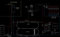
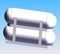
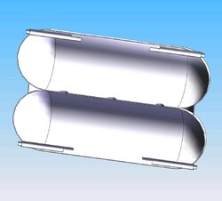
This is my version of a 'simplest system' with a few different twists. Nothing new over in Northern Europe. The storage tank is a couple 500 gallon propane tanks welded together to make what I referred to in an earlier post as a 1000 gallon hydraulic separator. Code-named "Tankzilla".

It's just a rough schematic sketch, except the heat storage tank itself which is pretty much pictorial. Just the "moving" parts are here that actually have to do with moving hot water when and where it needs to go. The little details that any good hydronics setup would have like air vents, iso valves, and such are not on this drawing. The radiant system's electronic controls are only in enough detail to remind me of how it all works as I think about the actual hydronics.

This layout has sat on my mind about like this for a while and now I ask that if there is something I missed or have configured in a dubious way that you all would be so kind as to point it out to me. Questions about anything that puzzles you are a good way to clarify my thinking so fire away.

Edit: Now that I posted this I'm not so sure I saved this old Autocad sketch properly. Hope you can read it.

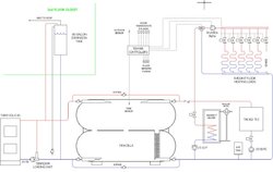
Here's a white background version that may be easier to read but the red hot water and blue cold water are color reversed. I'm going to work on fixing that.
 

Attachments

  • system review sketch.jpg
    system review sketch.jpg
    75 KB · Views: 911
  • system sketch white background .jpg
    system sketch white background .jpg
    79.2 KB · Views: 1,134
OK, I think the second sketch is now correct. Had to learn some new Autocad and Photoshop to do it. See if I remember it tomorrow.

Is that a stratification baffle in the tank?

Yes. At least that's the intent. Combination of vague memories of your description of the idea and some Euro websites and serendipity at the shop stock rack. 4" X 6" steel tube with lots of 1" holes that I will add. Helps to have access to CNC hole makers. That would be a lot of drill press work.
While I'm guaranteed to have low return temps from the radiant floors, I'm not sure that even with a tiny circulator on the indirect water heater it won't be coming back to the tank with temps higher than what's already in there on the bottom. Hoped it might climb the elevator, so to speak, without too much mixing. I've seen descriptions of using long mesh socks to do the same thing but how would you ever replace it if it wore out in a welded tank?
Also, as often happens, I'm leaving myself open to some unforeseen addition to the system that might return some inconvenient temp water. Trying real hard to get all the possibles covered before it's too late and the thing is stuffed up under the basement stairs and full of water.
 
You could save yourself a hundred dollars or more by eliminating all but one of the shut-off's on your tanks and one for your bypass. One each is really all you need unless you plan to remove or service the entire tank during operation. If you stop supply going into the tank you don't really need to shut-off the return coming out. Just a thought...being as Dutch as I am...1-1/4" full-port ball valves are not cheap....
 
Yes, stee, those full port ball valves add up. But the bypass valves are for experimentation and the others on the tank are actually isolation valves in case I need to work on the tanks if I have some bright idea or if I need to repair something in the middle of winter.

I was raised by my Scottish grandfather. The Dutch have nothing on a Scot from a depression farm in Northern New England. I'm trying real hard to avoid cursing myself for not anticipating trouble just to save a few bucks. It's not my history, so it's an adventure.
 
Nice layout. I like "Tankzilla"
From welding up my 2 tanks I ran into problems with the tank to tank connections. I welded the top tank first, upside down, connecting pipes sticking up in the air, flipped tank over and lowered it onto the bottom tank. The difficulty was trying to get the gun at a good angle on the connecting pipe and the lower tank with the top tank in the way. I would consider 1 pipe on each end for connecting, positioned where the flat tube of the tank body transitions to the domed end.
The big variable is, who is welding and with what equipment.
There were some posts back a month or 2 ago.
Rob
 
I wracked my brain for over 6 months trying to think of the best way to connect the two tanks and finally decided, since I have easy access at work to world-class welding (not me on the gun) that I would fasten the two together with a 6" wide skirt all around where they join. Cut some holes where they touch inside that skirt to join the interiors.
Welding torch access is tough if joining with pipes that are short. I wanted to minimize the overall height so this is best I could come up with at the cost of a 50ft. bead. The whole thing is fabulously overbuilt but it gets to be a game on 2nd shift to build wild stuff and "mod" things. 80MPH motorcycle sidecars from 50 gallon drums, etc.
It hasn't been assembled yet because, unlike most other businesses in Maine we've been working overtime for most of the last year plus and the weld shop has been to busy to take up floor space with anything but a drive thru project. It's worked in my favor. Gave me time to come up with more details I would have wished I'd done.
 

Attachments

  • TANKZILLA.jpg
    TANKZILLA.jpg
    53.2 KB · Views: 684
  • TANKZILLA section.jpg
    TANKZILLA section.jpg
    55.2 KB · Views: 670
with a few 3 way zone valves you could have a means to run the system automatically instead of manually shutting off valves.

This is the second drawing with two pipes up the the expansion tank? You really only want one as you don't want flow through that "heat emitter" It's just for expansion and the fluid can flow up or down one pipe.

Is the open tank in the upstairs closet to save the cost of a large bladder style expansion tank?

hr
 
So with all that work you are going to run unpressurized?

If they were pressure tanks why not use them that way? You already have had to deal with the bulking and heavy tank.
 
I like the idea of making the two tanks "one" via the skirt, My question is this: any issues with expansion/contraction as the thermocline passes from one tank to
the other with the tank coupled so close with the skirt? I suppose this is not a problem but there is a recent thread showing two tanks close coupled with pipe
(short pipes with no bends)and I'm thinking this may not be such a hot idea.

As a welder myself I would LOVE to have access to the equipment you have and I say no holds barred I would make it as fancy as you can dream up, Just
don't forget to report back as to what works and what don't... :cheese:

Ohh and as far as it being unpressurized it should make little difference as to the operation no? Just a minor detail...
 
Man you guys sure do like your welding. My personal opinion is that $400 worth of pallet racking is a MUCH more simple solution for stacking tanks. It's a no brainer essentially...as long as you get the proper size beams.

My install required zero welding....zero soldering too, as a matter of fact.

3169260980_cb0dbd8df1.jpg
 
with a few 3 way zone valves you could have a means to run the system automatically instead of manually shutting off valves.

If my plan works as well as I hope, I will never close any of those ball valves on the tank and the bypasses will remain closed. They are just there in case I need to work on the tank. I want to run the boiler hydraulically separated from the rest of the system. The boiler heats the tank, that's all. Some day I may have electronic variable speed control on the boiler circulator but I'm going to start out with just the Tarm control and the loading unit.

Is the open tank in the upstairs closet to save the cost of a large bladder style expansion tank?

Largely, yes. That combined with the fact that I have heated solely with wood all my adult life but never with hydronics. The idea of watching the pressure gauge rise as the system heats is something I'm sure I would get used to but I would rather avoid it. I prefer watching the gauge go from 11 to 13psi. The cost of a bladder tank big enough to minimize the pressure excursion like most have (many run too close to the pressure relief setting for my taste) would be painful. I got a new 80 gallon brand new 304 stainles steel tank off Ebay for about the cost of the metal in it. That kind of settled it.
This is the second drawing with two pipes up the the expansion tank? You really only want one as you don’t want flow through that “heat emitter” It’s just for expansion and the fluid can flow up or down one pipe.

There will only be water in the one pipe to the bottom of the expansion tank. The pipe to the top of the tank from near the boiler is an 'emergency' steam vent in case I do something dumb. I'll have the standard pressure relief valve on the boiler but I would rather not ever see it blow. The 3rd line from the side of the exp. tank near the top is just for my convenience in filling the system. My plan is that when the whole storage tank is as hot as it ever gets and I reckon expansion is at maximum, to use a fill valve down the basement from the house water supply to fill the system until the water in that expansion tank just overflows into that pipe about 10 gallons (about 8 inches) from the top. It will run down into the basement into a bucket when I open that valve on the end and I will know that the system is topped off at about the right point. Then shut off that ball valve. I don't want to hike up and down those stairs to do this. My version of remote monitoring.

So with all that work you are going to run unpressurized?
If they were pressure tanks why not use them that way? You already have had to deal with the bulking and heavy tank.

Steve, I actually inquired about the cost of having a custom tank fabbed up for this use and they surely wouldn't need to be as rugged as propane tanks but that's what we have surplus in this country so this contraption will weigh twice what it really needs to.
They will be pressurized. The static head of the water in the system will result in about 11 or 12psi at the boiler circulator. Pretty much the same as conventional residential 'pressurized' systems. The difference is that as the water heats up from a minimum of about 90F or so to maybe 200F, the pressure will only increase by a couple psi, not almost doubling like so many closed pressurize systems do. The disadvantage that I have to deal with is there will be some air getting into the system from the expansion tank. Reports from Europe via Hansson are that they commonly use this sort of system there without treating the water. I'm planning on using the same water treatment that Garn uses. Just cuz.

I like the idea of making the two tanks “one” via the skirt, My question is this: any issues with expansion/contraction as the thermocline passes from one tank to
the other with the tank coupled so close with the skirt? I suppose this is not a problem but there is a recent thread showing two tanks close coupled with pipe
(short pipes with no bends)and I’m thinking this may not be such a hot idea.

If the tanks were cut completely away inside the skirt it would definitely be a problem, just from the pressure alone. It is a good question and one I haven't been able to put a definite answer to. I ran it by my son, the steel bridge engineer, and he said he couldn't see any red flags. I'll be listening very closely for any noises as it heats up. And I think you are right. The sharper the thermocline, the more the issue will be noticed. I'm thinking an 1/8" gap between the tanks might be prudent. This is another reason I want to keep thr pressure from climbing unnecessarily above the minimum

Stee, I remember when the pallet rack idea was first posted here (maybe you, I don't remember) and I was jealous that I didn't have the headroom to do that. Another reason I wanted to get the tanks closer together was so I could get the bottom of the tank higher off the floor within the headroom I do have (as well as under the basement stairs to take up less space in what is my workshop). I'm hoping this rig will thermosiphon in a power outage. That's what the "loading units" are designed to do. They aren't used much yet in this country but are available now. Kinda pricey.

I just blew my savings this month getting the septic system and well in for this house and so I'm running low budget for the winter. Thank goodness the manager told me I can work all the hours I want this winter. I hope to get this rig in and working while it's cold enough to test it. I'm going to use Jebatty's idea of the tank as radiator until next year when I can afford the radiant stuff.

Thanks for all these questions, folks. Nothing seems to clarify thinking like explaining to others what you thought you understood.
 
Good desing Dave, not too much complicated.

Maybe add a low water cut-off in expansion tank for alert and control level.


And which model Tekmar controls ?
 
Maybe add a low water cut-off in expansion tank for alert and control level.

Yeah. I'm trying to come up with something to do just that. Any suggestions would be appreciated. The usual hydronic system low water cutoff devices are rather expensive for what I want. A float switch to operate a light bulb would suit me.

Tekmar 421 outdoor reset controller and a couple 335 zone manager modules ( 3 zones each). Mind you, I don't have these yet. That will be next year.
 
Elegant looking setup and AutoCad diagram DaveBP. If it works half as good as it looks and is designed, you'll surely do well heating your home.

Mike
 
Thanks, Julien. The real low water cutoff switches aren't as much money as I thought they were. I really need some kind of switch there because I might want to try floating some kind of oil in the surface of the water in the expansion tank to minimize the air getting into the water. But if the water level goes down over time and the tank was allowed to get really cold. Like during a mid-winter vacation (never done that but who knows) it might cool enough to suck the oil down into the system and that couldn't help anything.
 
OK, you are pressurized. So if your pressure/expansion tank has just a small vent it shouldn't loose that much to evaporation.
 
So if your pressure/expansion tank has just a small vent it shouldn’t loose that much to evaporation.

The vent is not very big but on 1100 gallons in the system the expansion is on the order of 40 gallons each firing. So the expansion tank is 'breathing' in and out every day. I don't think the evaporation loss will be great, as you say. I just like to anticipate my own tendency to absent mindedness. Probably something that need to be checked every month.

Just checked out your website, Steve. I used to have a portable sawmill. An old Mobile Dimension mill. All manual, no power nothing. VW engine with a pull cord to start it. My wife could run it herself and,yes, start it, too.
Used it mostly around home sawing lumber as we cleared land. Built our buildings with it and sold some. Only sawed off the place enough to pay for the rig. We never mention that mill without a smile coming to our faces. Of course, we were a couple decades younger then.
Yours looks like a proper setup. Hope you can do well with it.
 
Are you worried about dissolved Oxygen in your expansion tank? The use of an elevated tank for static head is a good clean & inexpensive way to provide surge volume and pressure. The down side is the cool water will absorb O2 - which will be introduced into the circulating water during cool down (outsurge). Dissolved O2 is murder on carbon steel.

You can get around the problem by keeping the expansion tank at or near boiling (decreasing the solubility of air), or keeping a N2 blanket on it (which doesn't seem to practical).
 
Are you worried about dissolved Oxygen in your expansion tank?

In a word, yes. I'm concerned more than worried, though.

I would resent the heat loss from the tank if it were near boiling and I don't want to have to insulate it so much as that would require. I'm probably going to use water treatment chemicals like some open boilers use. I read (it would be nice to have it confirmed my a Garn owner) that Wood Boiler Solutions provides the treatment chemicals used by Garn and some others that are also vented to atmosphere. Their web site is very informative and they seem to be a lot cheaper than some others.

http://www.woodboilersolutions.com/

The best program will be to test it annually to be sure that the chemistry is stable and add whatever the tests suggest to maintain it. I believe that is part of owning a Garn.

Any Garn owners out there care to corroborate or contradict that?

I will research more on the idea of floating some oxygen impermeable oil on the surface in the tank. One of our European members says some do that in Scandinavia. He also says that he doesn't know anyone that uses water treatment chemicals.

I reckon I can also panic out and get a big bladder tank at any time but they are fierce money even from those I've seen on Ebay.

Open-vented systems used to be common here in the states and still are in Europe. I'm cynical enough to think that the self interest of unions and manufacturers had as much to do with the changes in practice and code policy as much as any real problems. I would love to know more of the history of hydronic systems in the states but the backroom politics rarely makes it into the official versions.

But the advantages of a sealed bladder expansion tank over a vented one are not lost on me. It has as much to do with my contrarian nature as anything else, probably.
 
What's needed is two things: a low pressure expansion tank; and a perfectly reliable large diameter, low-pressure relief valve.

The attic cistern supplies both nicely. System pressure is referenced to atmospheric at some fixed elevation, and the system can simply vent steam to the atmosphere at the top of the system whenever pressure at the boiler overcomes the static pressure of the water column; and the expansion vessel is likewise referenced to atmospheric.

But an attic cistern exposes the system to oxygen. A bladder-type expansion tank vented to atmosphere would be nice, but they are a little pricey. And they're pricey because using one would be overkill, being rated at upwards of 125 psi and all we need is less than one psi.

So how about a roll-your-own bladder-type referenced-to-atmosphere expansion tank? Maybe buy a replacement bladder and fabricate an open-top tank with flanges to accommodate the bladder.

Another idea would be to use a tractor-trailer or implement inner-tube with a pipe connected to its bottom side with flanged nipple and a flange plate inside the tube. And on the top side another connection to allow for bleeding air off.

Pressure relief would be a pipe elsewhere, extending above the bladder system, vented to atmosphere, possibly with a open caged billiard ball check valve to keep that air-tight as well.

The best I can come up with for maintaining water level would be to "keep an eye on it" and make sure there's plenty of water in the system when it is cold.

--ewd
 
A bladder-type expansion tank vented to atmosphere would be nice, but they are a little pricey. And they’re pricey because using one would be overkill, being rated at upwards of 125 psi and all we need is less than one psi.

I watched a couple nice ASME B & G full-acceptance bladder tanks go by on Ebay that would have been perfect for just this and it was my hope to do it that way but even used they went by for auction fever prices. And new they are a couple thousand dollars in the size I need. When I saw this 304 stainless tank come up and I got it for the price of the metal in it I just went with the flow. I will keep my eye out for the next perfect solution but if another comes up it will still be atmospheric vented in the same spot in the upstairs closet.

Fabbing up a full acceptance type bladder tank would be fun but my plate already runneth all over the floor. Maybe after everything else is up and running. It could be the service pack 1 upgrade. The low tech answer would be a layer of oil on top of the water in the tank. But that introduces its own issues.

It's the sort of project I keep my eyes out on Ebay for, though. One of the probe sensor low water cutoff switches will watch my water level more reliably than I ever would.
 
On the topic of feed and expansion cisterns, you might want to review the plumbing relative to the circ pump and blow-off piping.

Here's the best discussion I've found.

http://www.pumptool.co.uk/Position.html

They make a good argument for putting the circ pump on the boiler outlet side, but that complicates the use of a three-way thermostatic mixer for maintaining minimum boiler return temperature.

--ewd
 
Thanks, ewd. That is an intriguing read, and very pertinent to what I'm doing.

I am going to use the Termovar loading unit ( it's sitting in its box on the boiler as we speak, so why not?) that gives me no option about where to put the boiler circulator. Seems the loading units, of whichever make, are the normal setup in Europe and I take practices over there to be highly refined when it comes to downdraft gassifier wood boilers.

The article you posted seems to concern high head pumps. And I can see what I never seriously considered before, that the pump could overshoot water into the exp. tank through the safety vent and turn the expansion tank into an aeration tank. That would be a disaster over the long term. I'm not sure that the head from a Grundfos 1558 (the model that it has built into it) will work up that kind of pressure in such a low head circuit as I'm putting together.

My setup is going to go from 1 1/4" pipe near the boiler to 2" as it goes to the heat storage tank. This article makes me think it might be better to run the safety vent up from nearer the storage tank than the boiler, to lower most of what little pump head there is before it gets to the safety vent line. Or perhaps even down next to the expansion line. Too little sleep this morning to come to any conclusions.

I'd welcome any other thoughts you have on this and thanks again.
 
Status
Not open for further replies.