
Boiler piping schematic with pressurized storage
- Thread starter tuolumne
- Start date
-
Active since 1995, Hearth.com is THE place on the internet for free information and advice about wood stoves, pellet stoves and other energy saving equipment.
We strive to provide opinions, articles, discussions and history related to Hearth Products and in a more general sense, energy issues.
We promote the EFFICIENT, RESPONSIBLE, CLEAN and SAFE use of all fuels, whether renewable or fossil.
You are using an out of date browser. It may not display this or other websites correctly.
You should upgrade or use an alternative browser.
You should upgrade or use an alternative browser.
- Status
- Not open for further replies.
Nofossil
Moderator Emeritus
master of sparks said:What turns on pump "A"? Does it turn on with the 140f control on the EKO? If so what if the tanks are at 180F and the boiler hits 150F from a cold start?
I'm assuming pump A is controlled by the EKO controller. Why would you build a fire if the tank was at 180? If you did, you'd be pushing 150 degree water into the tank, assuming that there wasn't enough demand from the secondary loop to take all of the flow from pump A.
Also, depending on the flow pattern through that 3 way zone valve it LOOKS like the two pumps will be in series when the ZV flows straight though?
Also what causes flow into the buffer tanks?
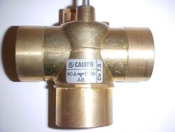
As I understand it, that's not a 3 way zone valve - it's a mixing valve. It has a hot in, a cold in, and a mix out. It will balance the two inlets to achieve the desired outlet temp, just as with the Danfoss that he's using for boiler inlet protection.
Because it's a mixing valve, it will have the effect of limiting flow from the hot inlet most of the time. Unless there's an enormous heat load from the zones, a good portion of the output will be recycled from the inlet. It's set for 140 degrees, and the hot inlet will always be hotter than that if pump A is running. Therefore, the excess output of pump A goes into the tanks.
The two pumps would be in series in effect on a really cold start. If the boiler outlet is 150 and the zones are cold, the mixing valve will almost be a straight connection from hot inlet to mix outlet. That would be the desired behavior.
Bob Rohr
Minister of Fire
What are the temperature requirements of the heating loops? I'd guess you want 160F or more if the heating emitter are baseboard or fan coils. Maybe 140F for panel rads.
So the upper thermostatic valve would be set to 160, let's say. Really the indirect would be better back at the boiler loop via closely spaced tees for the hottest, quickest supply. If the upper thermostatic is set to 180 so the indirect tank could get plenty of BTUs, then why have a thermostatic there at all if 180 is desired for all the high temperature loads?
I'm still unclear on how or what regulates the flow through the buffer? And does the flow direction change through the buffer when the boiler circ is off to "unload" any heat from the buffer? Or will the buffer always run at the boiler temperature? The pressure drop through the upper 3 way will always be higher then the pressure drop through the buffer. Seems like a balance valve may be needed to assure the 3 way gets enough flow to supply it's loads?
I guess what is needed is some temperature numbers and required gpm through the various circuits to really get clear on flows at various loads on or off.
hr
Nofossil
Moderator Emeritus
master of sparks said:What are the temperature requirements of the heating loops? I'd guess you want 160F or more if the heating emitter are baseboard or fan coils. Maybe 140F for panel rads.
So the upper thermostatic valve would be set to 160, let's say. Really the indirect would be better back at the boiler loop via closely spaced tees for the hottest, quickest supply. If the upper thermostatic is set to 180 so the indirect tank could get plenty of BTUs, then why have a thermostatic there at all if 180 is desired for all the high temperature loads?
I'm still unclear on how or what regulates the flow through the buffer? And does the flow direction change through the buffer when the boiler circ is off to "unload" any heat from the buffer? Or will the buffer always run at the boiler temperature? The pressure drop through the upper 3 way will always be higher then the pressure drop through the buffer. Seems like a balance valve may be needed to assure the 3 way gets enough flow to supply it's loads?
I guess what is needed is some temperature numbers and required gpm through the various circuits to really get clear on flows at various loads on or off.
hr
As described in an earlier post in this thread, he only needs 140 for all loads in the secondary loop except DHW. Looking at different approach for DHW. At 140, the mixing valve controls flow to the buffer. The secondary pump should ensure that enough flow is pulled from the primary loop.
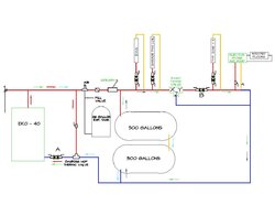
Wow, there has been a lot of discussion while I was away! There are two distinct loops. Regarding the situation where the buffer is at 180, I would not likely be lighting a fire under those conditions. Pump A is controlled by the boiler, and always runs when the boiler is producting water hotter than the setpoint. The purpose of the "balancing valve" on the boiler loop is to restrict flow somewhat. This will ensure that pump B circulates through the buffer and not the outer loop. Retrieval from the buffer draws off water in reverse, taking the hot water off the top first. I'm going to attempt a drawing incorporating the sidearm. I have never seen one, but my plan would be to have an outer shell of 1-1/2" copper that has a 1-1/2x1-1/2x1-1/4 tee at each end tying it out to the main 1-1/4" loop. In each tee would be a 1-1/2"x1/2" reducer. A 1/2" pipe would run through the middle and into the drain/pressure relief as Eric described. Is 1/2" big enough for the inner? Is my description of the construction correct? I am also going to try stacking the buffer tanks in reality, so I'll draw them that way too.
Edit: for whoever asked, I got the Danfoss from Mark at ahona, I think he gets them from mcmaster.
Edit: for whoever asked, I got the Danfoss from Mark at ahona, I think he gets them from mcmaster.
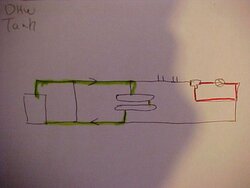
OK, here is the mod. I am mostly explaining this to myself; you experts please chime in. If these assumptions are incorrect, please let me know. Any time the boiler is charging the storage tanks, water flows through the sidearm. When the boiler is cold, water will circulate through the loop marked with red arrows. As the Danfoss hits 140 and starts to open up, water begins to follow the light blue arrows and begins to charge the buffer tanks. If any zone calls, pump B will begin which causes water to follow the path of the green arrows. The mixing valve would be set at 140 degrees since that would supply the highest demand for those zones. The DHW and fan coil would always get water however hot the buffer or boiler has to offer. If the demand is low (one small zone calling) some return water will be drawn back into port Z of the mixing valve. The reduced demand at port X would cause some flow from the boiler to divert through the buffer along the light blue path. When the boiler grows cold, pump A will stop. When zones call, pump C will draw water from the buffer tanks along the path of the black arrows. Does this all work?
Attachments
Bob Rohr
Minister of Fire
Looking better. A few thoughts. I'd move the air purger before the bypass. While not a huge deal it would see the highest temperature (best air removal spot) and be a good location for the point of no pressure change (expansion tank connection).
If your DHW is the most critical load, pull it right off the boiler as another parallel loop. Prioritize it with a double pole relay to shut down any other loads until it is satisfied. It will perform best with all the boiler flow flow and the hottest possible supply temperature. Unless it is a huge tank, 100 gallons or more, it shouldn't hold the boiler in condensing mode too long to be a problem. You could probably lose the sidearm also with a priority DHW zone. Cost saving if nothing else. And some of the indirects are not rated for the high temperature the sidearm may supply.
Remember for the closely spaced tee (loads) the pump down stream will need to run to assure a constant supply of hot water across those tees. Elsewise it will just recycle the same temperature.
Do you have all your volumes calculated to size the expansion tank?
When will you start the piping? You put some serious thought into the plan")
If your DHW is the most critical load, pull it right off the boiler as another parallel loop. Prioritize it with a double pole relay to shut down any other loads until it is satisfied. It will perform best with all the boiler flow flow and the hottest possible supply temperature. Unless it is a huge tank, 100 gallons or more, it shouldn't hold the boiler in condensing mode too long to be a problem. You could probably lose the sidearm also with a priority DHW zone. Cost saving if nothing else. And some of the indirects are not rated for the high temperature the sidearm may supply.
Remember for the closely spaced tee (loads) the pump down stream will need to run to assure a constant supply of hot water across those tees. Elsewise it will just recycle the same temperature.
Do you have all your volumes calculated to size the expansion tank?
When will you start the piping? You put some serious thought into the plan
Thanks. The pressure tank is sized for all of my volume. It has a 1-1/4" connection, so I tied it in adjacent to the air purge, but I can run out of the bottom of my air purge with a smaller pipe and transition at the tank. I can't move it closer to the boiler, because the high point in my system is actually right where I show the air purge. I have some 3D sketches, but they're too big to post when I scan them. I want the water heater set at 110 or so since I will also have a fossil fuel tied into the same primary loop - I thought it would be just before the DHW, and just after the radiant zones, therefore skipping the buffer tanks. The sidearm would allow me to keep the DHW at a higher temperature most of the time without running an extra pump to do it.
Pump B will always be running when the zones call. Does that satisfy the needs of the closely spaced tees?
I'm wrapping up the heat distribution now, so I'll probably start piping the boiler later this week.
Pump B will always be running when the zones call. Does that satisfy the needs of the closely spaced tees?
I'm wrapping up the heat distribution now, so I'll probably start piping the boiler later this week.
Bob Rohr
Minister of Fire
The one nagging question I can't seem to get straight is the flow through the buffer. In my mind I see to potential for flow as shown in my green arrow, and flow around the system mixing valve in red.
Water is lazy and takes the path of least resistance. I'm not understanding the dynamics to induce some, if any flow to the red loop from the boiler/ buffer loop. The flow through the mix valve will depend on the % it is open at a given time. If it sees 180 on the hot side, for instance, it will blend cooler return to try and target that 140. In that mode you will have little or any flow between the green and red loops. It may not be an issue? But the loads between those two loops may not do much (DHW and Garage)
I understand this is a common "wood boiler" schematic, I still feel a true P/S as I showed on my sticky post really address ALL the hydraulics at any given time and assures everyone is satisified and balanced.
I'd consider a flow setter, or at least a globe valve in the piping to the buffer to allow some restriction to be introduced IF you don't get enough flow to the red loop.
Also check protection on all takeoffs to the heat load and radiant load. I use the circ with built in checks on one side and a soft seat check on the return.
I calculate 8 gpm at about 4 feet of head for the boiler circ (20 degree delta T). A Grundfos 15-58 on speed two. Same for the system pump. Zone pumps need to size to the gpm and pressure drop. Possibly on speed 1?
hr
Attachments
Right, if the DHW is calling, pump B is running. However, the other zones are using any hot water, so pump B starts cycling in the red loop endlessly. Oops. If I move the pump to the left of the hot demand zones (actually drawn this way in my 3D layout) the mixing valve won't work right....will it? I almost need a primary seconday loop off the primary loop....too many pumps gobbling up kilowatts. I don't really care about my radiators running short cycles at 180 degree water as much as charging the buffer at the same time when heat is available. With your primary/secondary diagram, I don't see how I can draw off the buffer in reverse for retrieval.
Nofossil
Moderator Emeritus
tuolumne said:Right, if the DHW is calling, pump B is running. However, the other zones are using any hot water, so pump B starts cycling in the red loop endlessly. Oops. If I move the pump to the left of the hot demand zones (actually drawn this way in my 3D layout) the mixing valve won't work right....will it? I almost need a primary seconday loop off the primary loop....too many pumps gobbling up kilowatts. I don't really care about my radiators running short cycles at 180 degree water as much as charging the buffer at the same time when heat is available. With your primary/secondary diagram, I don't see how I can draw off the buffer in reverse for retrieval.
My thought is that this is not a problem. First scenario: everything is cool, no flow. 3-way is open x>y, because it wants to be at 140. DHW demand kicks in. Pump B and the DHW pump come on. The water coming out of the DHW zone is below 140, so the 3-way stays open x>y. All good.
Next scenario: Everything is really hot, no demand in red loop. 3-way is almost straight z>y. DHW demand kicks in. At first, DHW mostly recirculates, but there is always some flow through the 3-way since the red loop is at 140 and has to be losing something. as soon as a bit of the cooler water hits the 3-way, it flips to x>y. This scenario is worst case, and wouldn't likely happen in real life if you had the sidearm, since the only way that everything would be hot is if you'd been circulating hot water, which would have heated the DHW via the sidearm.
Probably makes sense to have the DHW and garage taps near the 3-way to minimize this potential problem.
In my world, the DHW hasn't had to call for heat since October. Family of five with frequent company, 40 gallon indirect.
My Superstor has no problems at 160+ degrees, but it would be prudent to make sure your indirect is OK up to 180 or so. I'd not move the DHW zone over to the boiler loop since you'd want to be able to heat it from storage.
I am not sure the sidearm will work now that I've laid out the equipment. I need to run my main loop way out of its way to do the sidearm. I have a superstor ultra 80 gallon tank. My plan is to pipe in the boiler loop which is known and get my tanks set to see where things are at. I need some concrete progress to help clear my head!
Nofossil
Moderator Emeritus
tuolumne said:I am not sure the sidearm will work now that I've laid out the equipment. I need to run my main loop way out of its way to do the sidearm. I have a superstor ultra 80 gallon tank. My plan is to pipe in the boiler loop which is known and get my tanks set to see where things are at. I need some concrete progress to help clear my head!
Yeah, I feel like it's time to start building. A sidearm is great if you can do it, even if it can't be at the optimum spot in the primary loop. Any time that water is going through it that's hotter than the DHW, you're getting heat. It's one of the things I wish I'd done. Instead, I have a relay that opens my DHW zone valve when I have some extra heat, and heats it to 160. That works, too.
Biggest reason for obsessing about hot water: that's what will gate your fire interval and/or use of fossil. You may be able to get usable heat out of your radiant and panels with storage temps below 120, but that's marginal at best for heating DHW. When you run out of DHW you'll hear about it.
Your drawing doesn't show your future fossil boiler, but I assume that you're comfortable with putting it in parallel with the EKO with its own circ. The only reason that I bring it up again is that you would want to make sure that the EKO circ has a check valve so that water isn't pushed backwards through the EKO when the fossil is running. In the 'as drawn' without the fossil, that check valve would not be necessary.
By the way - do you have a part number / source / rough price for the Danfoss?
Bob Rohr
Minister of Fire
Yeah, I agree you are on the verge of over thinking the system. Every system could, or should be tailored to the owners needs wants and desires. Many way to accomplish your goal.
It helps to define how much DHW, how fast, and how often. My 80K Lochinvar Knight LP boiler will keep up with my shower running non stop. for many a 2- 2.5 gpm DHW flow is plenty. Really no need for a lot of storage in my case. I have solar preheat on all my systems, and the house has a dual coil 60 gallon tank for solar assist and boiler back up. All summer long the boiler is shut down.
DHW via wood heat is or can be more involved if you want to cover all the options for hw, buffer, multiple heat sources.
The same holds true for your heat loads, what are they on design day. with tht info pump, mixing valve, needed storage, burn cycles, etc can be calculated and designed around.
Like most on this list I tinker and experient also. I've built plenty of trial and error HX systems over the years. I have learned that you can pretty much define and build most systems on paper to accomplish exactly what you need them to do. It cuts down on the solder and un-soldering phase.
I am impressed with nofossils control system. It is key to a well behaved hydronic system. The more data and the more ability to react and change the more efficient your system will operate.
Mild to wild are with plenty in between with system design and installation.
Stop thinking and start soldering. Nothing you plan on doing can't be re adjusted and tweaked later.
Here is my current approch with a EKO 40, circular primary loop, 500 gallon Lp storage and a few setpoint and differential controls to load and un-load the various components. The onboard 140F control in the EKO protects the boiler from cool returns, no thermostatic valves used any where. A variable speed outdoor reset control, on a 15-42 Grundfos circ adjusts the temperature to the radiant slab zones in the shop and office.
Solar gets added as I score take-off freebie panels. so far 1- 4X10 does DHW preheat.
hr
Attachments

Eric Johnson
Mod Emeritus
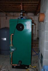
Hot rod, yours is the second pro installation I've seen on this board that has the chimney extending down to the boiler exhaust outlet. Most of use black stove pipe. What's the reasoning behind the extra expense?
Nice to see I'm not the only one who parks tools on his boiler.
Nice to see I'm not the only one who parks tools on his boiler.
Nofossil
Moderator Emeritus
Impressive system, MOS!
What is the 'onboard 140 F control' on the EKO that you refer to? Mine has no such thing, and my sense of elegance is offended by the bang-bang control system that I have at present (using a zone valve). I'm adding a multiple speed pump (Grundfos under computer control) to help, but how else could you do it without a tempering valve?
What is the 'onboard 140 F control' on the EKO that you refer to? Mine has no such thing, and my sense of elegance is offended by the bang-bang control system that I have at present (using a zone valve). I'm adding a multiple speed pump (Grundfos under computer control) to help, but how else could you do it without a tempering valve?
Nofossil, I got the danfoss from Mark at ahona. It is 1-1/2" female, but I believe a 1-1/4" is available...I wish I'd gotten that one since the rest of my system is 1-1/4. It is also available in several pre-set temperatures. Mine is 140 degrees F. I think Mark gets them from mcmaster carr. By the way, he said he is at some farm show in Barre this week. I don't know how close you are to there.
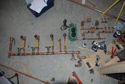
I'm finally turning some of the schematics into reality. This doesn't look like much for a days work, but I'm fairly green at pipe fitting. The boiler piping is held up on some tees I'm waiting for for the temperature probes. What you see is the boiler circ pump on the return; that tee on top is just keeping junk out. On the floor you see part of the primary loop with supply/return lines for the secondarys. On the right side is the distribution for the two radiant zones.
Attachments
solarguy
New Member
You would weld a schedule 40 nipple on to the tank or weld a threadolet.
Personally, I like threadolets better.
Personally, I like threadolets better.
Yes and no Eric! Sacrifice one of your fittings and test it - then again if you begin and fail you can grind the offending weld and fitting off just like Windows Restore.
Flow will be enhanced if you grind a radius inside the tank easing the sharp edges to the outside! But thats a lot of work and most do not care.
I make my own Thread outlets - If you have pipe coupling fitting already in the correct size and they are the type that are not threaded all the way thru - look in side - Do the threads stop in the middle and is there a narrow ring of un-threaded area?? IF YES -- Bravo - quality fitting - if no - all is not lost they work
Cut the coupling in half
Place the cut end to the tank and weld that water tight - Do you weld water tight?? I used to be able to - then I got old my eyes went south and I shake too much. Poor me - who cares.. Tack one side - weld 1/4 diameter on the fitting on the other - one inch or what ever is the least length - go back to the other side begin your weld 1/2 inch away from the tack and carry the weld puddle across and well over the tack to bury the it in the new weld. STOP peen your welds. Start in the middle or one inch away from the first full weld and weld to the first weld - do not stop weld over it by 1/4 inch then stop - peen the weld - continue stitching like this welding over the previous to seal each stich to the next and teh last begin on the old and carry the puddle over and past the neighbor.
Fill the vessel with water to within a 1/2 inch of the weld to limit your explosion danger or fill the vessel with inert gas as you weld to prevent flash out - these heavy tanks will likely not shatter if a the old vapor ignites BUT you will be in for a ride if it does - and maybe a little less chest skin,
Hove fun - be safe let us know your OK !
!
Kind Regards
Sting
Flow will be enhanced if you grind a radius inside the tank easing the sharp edges to the outside! But thats a lot of work and most do not care.
I make my own Thread outlets - If you have pipe coupling fitting already in the correct size and they are the type that are not threaded all the way thru - look in side - Do the threads stop in the middle and is there a narrow ring of un-threaded area?? IF YES -- Bravo - quality fitting - if no - all is not lost they work
Cut the coupling in half
Place the cut end to the tank and weld that water tight - Do you weld water tight?? I used to be able to - then I got old my eyes went south and I shake too much. Poor me - who cares.. Tack one side - weld 1/4 diameter on the fitting on the other - one inch or what ever is the least length - go back to the other side begin your weld 1/2 inch away from the tack and carry the weld puddle across and well over the tack to bury the it in the new weld. STOP peen your welds. Start in the middle or one inch away from the first full weld and weld to the first weld - do not stop weld over it by 1/4 inch then stop - peen the weld - continue stitching like this welding over the previous to seal each stich to the next and teh last begin on the old and carry the puddle over and past the neighbor.
Fill the vessel with water to within a 1/2 inch of the weld to limit your explosion danger or fill the vessel with inert gas as you weld to prevent flash out - these heavy tanks will likely not shatter if a the old vapor ignites BUT you will be in for a ride if it does - and maybe a little less chest skin,
Hove fun - be safe let us know your OK
!Kind Regards
Sting
My local supplier has "weldolets", thanks for giving me a clue what to ask for. Thanks for the details. The tank has been pressure washed, and I had planned to blow air through it during the welding. I cannot do water until I get the boiler going, as any water I bring into the house now will freeze. The well is in, but I havn't dared to bring any water up! I could run tractor exhaust through the tank and back outside if that would be better than air. Opinions?
Place the flame of a small propane torch in the exhaust stream of the tractor and MAKE SURE that the propane flame does not enhance the products of combustion because the donor vehicle is running rich. IF the propane torch is extinguished - so much the better. but try till YOUR satisfied. I have welded tanks using exhaust gas from a know good source like this but you must trust that source -
Think of it like this - if you pressurize a tank to 30 psi of water - and a weld ruptures - you get a big leek and a little splash. but if you pressurize it with the same PSI of air - you can expect the same result as when the tire on your truck blows out at 30 PSI BIG BANG...
Liquid is always the preferred safety for this - but work arounds are necessary for some things
put as much pipe on the exhaust as you can to cool the stream before switching to flexable hose or the exhaust heat could melt the hose and you will suddenly loose your gas shield in the tank
solarguy
New Member
I'm not sure about blowing air thru the tank while welding to disipate residual propane fumes.
We fill existing propane tanks up with water, then drain them prior to even drilling holes in them let alone welding. During the fill process, any residual propane fumes get purged from the tank.
Once you drain it any residual liquid is history, you are 99.9% assured you are not going to blow up
We fill existing propane tanks up with water, then drain them prior to even drilling holes in them let alone welding. During the fill process, any residual propane fumes get purged from the tank.
Once you drain it any residual liquid is history, you are 99.9% assured you are not going to blow up
- Status
- Not open for further replies.
Similar threads
- Replies
- 9
- Views
- 2K
- Replies
- 0
- Views
- 955
- Replies
- 10
- Views
- 2K
- Replies
- 16
- Views
- 5K