Thanks for the great replies so far.
EWD - I love the idea of pulling the shop hydronic off the house loop return. It eliminates the three way valve, and when the shop hydronic is running alone, it keeps my house W-A HX and my sidearm waterheater hot. I'll get a certain amount of heat into the furnace ducting just from convection off the hot W-A HX without the furnace fan running.
The reason I was thinking of a Taco variable speed setpoint pump on the boiler is to maximize the stratification in the storage tanks. Seems guys have problems matching gpm with the tank temps when they get close to saturated. Initially I'd only need 6.2 gpm ( 140k/500/(185*-140*)) but at the end of loading the tanks may need up to 14 gpm (140k/500/(190*-170*)). I suppose if the tanks are really well stratified it wouldn't matter as the change from 110* water at the bottom to 180* water would happen in a small number of gallons ( sort of like my electric water heater, when it runs out, it gets cold FAST ).
Bob- The only reason for the valves at the tanks are to isolate for whatever maintenance reason, at the end of shoulder season I could drop down to one tank charging, etc.
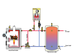
I'm puzzled why the tanks in their current configuration don't work as a 'hydro seperator'. What functionally is different if I happen to draw the load piping on the right hand side of the 1000 gal tanks? Lets say my boiler is producing 185* water and 6 gpm headed uphill towards tanks and loads - if I'm pulling 8 gpm in my house loop, 2 gpm pulls off the top of my tanks. If they are charged at 185*, great.... if they are cold ( 110* ) my 8gpm water to house is blended, but still 162*.
I don't see the need for any "load balancing and changing settings" with what I have here. The only variable is what return water temp is shoved back into the bottom of my tanks. I'm probably missing something.....
Regarding balance valve on feed to Danfoss valve - I'm tickled you pointed that out. I've always wondered what in the world it would ever be used for, but it seems like every diagram has one, so I figured I was too dense and better put one in just in case. If you've tested them and have a recommendation on what model TV to use, I'm all ears.
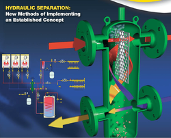
Here is what I understand about a hydraulic separator. It basically provides a wide spot in the piping. The key is a 3-1 ratio. The center barrel needs to be 3 times the diameter of the pipe connected to it. This allow flows to cross within the device without pushing flow thru the opposite side. So, in fact, different sized circs can pump through a separator without adding flow to each piping system.
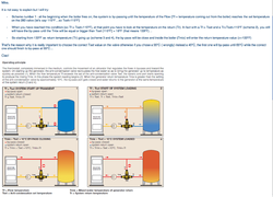
With a tank that size the ports would not need to be direct opposite on the tank, as long as there was some separation to allow multiple flows. I've built some of these separators with clear plastic to demonstrate the concept in my training. A large high head pump on one side, a smaller one on the other. red food coloring in one side, run that pump for 20 minutes and no color moves into the other side. Then blue color in the B side, turn off A side pump and the colors stay the same. Only when both pumps run does the color blend. The amount of blending of temperature depends on the two different flow rates. The formula in I-dronics 1 tell how to calculate the mixed temperature, but you need to know flow rates.
If you have a means to calculate the pressure drop in the various zones you can determine with a pump curve and system overlay, exactly what the operating point is on the pump curve, then you will know exactly how many gpm is flowing in all the zones.
Or add a flowmeter that will give you a visual of how much flow is moving in various loops. The only way to assure you have the flow you want, or need, in every zone is to calculate all the resistence, or add a flow setter/ balancer to force it into the desired operating point. The system will never just self balance and provide the flows you write down on the design sheet
")
. That is why engineers always include flow setters on larger or complex piping systems, you need to balance systems with complex piping. There are actually companies that specalize in balancing hydronic systems and on most large jobs the M.E. require a balance contractor sign off.
Then you need to decide what type of balance valve. In your drawing I'd look at a PIBV pressure independant balance valve. You buy this valve with the flow rate you need speced out. This type of valve has a spool that slides around and assures that piping loop ALWAYS gets the correct GPM regardless of how many other zones or pumps turn on and off.
Even with hydraulic separation you may need balance valves on some or all of the piping zones, or at least a flow meter to see where the system is operating.
In many cases the various piping layouts we see here work and move heat energy, and good is good enough, trial and error design.
Systems that short cycle, make velocity noise, wear out pumps, have in-adequate heat output, air lock, etc... these are all flow related problems that can be determined or corrected with flow meter and balance valves.
hr