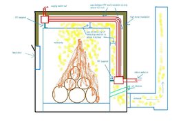
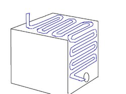
I've included a drawing of a Seton/GW side view showing how the HX is positioned inside the unit. Anyone who has to clean these beasts know how hard it is to get at the water tubes without taking the side and perhaps top panels off. Then you have to worry about ripping the Kaowool all to hell in the process. When I first took mine apart last year, I found the outer row of tubes in the back (vertical section) was essentially glued to the Kaowool with creosote and gunk. One of the reasons why was that there was very little room between the outside row of water tubes and the Kaowool itself. So it was easy for that small space to begin to fill in and shut off any air flow to the outside of that row of tubes, which of course means little if any heat transfer.
When I put the back panel back on, I did not replace the 2" mineral wool layer, but just added an extra 1" layer of kaowool. So instead of 3" total insulation (2" mineral wool and 1" kaowool) I just had 2" of kaowool, leaving me an additional inch of air space between the water tubes and the insulation and hopefully no clogging up and better heat transfer.
But now when I look at this HX, would it not work better if it was moved closer to the firebox? If you lowered AND moved forward the HX, would it not work more efficiently? When you look inside the unit during a burn, you see the flame path go up and then quickly over the back of the refractory and down to the stack outlet. But the HX sits very high in the firebox and also far back from the back of the refractory on the vertical section of tubes. It seems to me that if the water tubes were closer to the actual flame path it would be much more efficient?
Currently there is only about 1/2"-3/4" of room between the top/outside row of water tubes and the insulation. I would think if the HX was lowered by about 2" and moved forward about the same 2", much more of the HX would be in the flame/exhaust path.
Any thoughts on this? I plan on pulling the HX out of my unit this spring to examine it and I could modify it at that time.
thx, Pat