Pressurized Storage Piping Idea

  • Active since 1995, Hearth.com is THE place on the internet for free information and advice about wood stoves, pellet stoves and other energy saving equipment.

    We strive to provide opinions, articles, discussions and history related to Hearth Products and in a more general sense, energy issues.

    We promote the EFFICIENT, RESPONSIBLE, CLEAN and SAFE use of all fuels, whether renewable or fossil.
Status
Not open for further replies.

chuck172

Minister of Fire
Apr 24, 2008
1,045
Sussex County, NJ
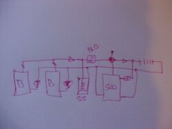
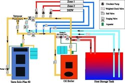
I've bugged nofossil long enough, it's time I try to post this diagram on this forum to get other opinions. I have a TarmSolo40 piped parallel to an oil boiler. I also have an indirect superstor water heater piped to its own zone off that oil boiler. Tarm shows this piping layout on page 20 of their installation manual. It is their preferred layout. Unfortunately all their storage drawings seem to show storage with their primary/secondary set-up. I'd prefer not to alter any of my existing piping if possible. I'd like to add a 500 gallon propane tank for pressurized storage. I may add another in the future if needed.


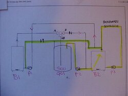
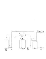
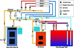
Using a 3-way zone valve e.g. honewell VC series: All circulators are taco 007

Heating Zone or SuperStor calls for heat:
Port B on zone valve closes, AB opens sending HW to oil boiler. HW goes through oil boiler to heating zones or superstor.

Oil Boiler satisfied, Tarm hot:
Storage tank charges.
port AB closes, B opens wood boiler HW circulates through storage. The Tarm will always pump hot water to storage whenever the oil boiler is satisfied and the wood boiler is operating at 160 degrees or more.
Wood boiler cold, storage hot, oil boiler zone or indirect water heater calls for heat:
HW is circulated through storage to oil boiler.

Tarm cold, Storage cold, zones call for heat:
Oil burner kicks on (oh no!)

I know this idea needs alot of work. I'd really like to hear some comments. This piping layout can be very simply adapted to my basic no storage parallel set-up.
 

Attachments

  • Press. Tank Storage.jpg
    Press. Tank Storage.jpg
    21.8 KB · Views: 887
  • boiler.jpg
    boiler.jpg
    16.3 KB · Views: 707
kinda early, but I think this is what you are after?

I've given this DHW priority with a zone valve. so when ever there is a call for DHW all energy, from which ever boiler is firing, recovers this load quickly. then the flow goes straight through the 3 way ZV to the loads. when the loads are satisfied, the 3 way zv starts charging the buffer. If, or when the buffer is up to temperature, its circ would start and run the loads. A double throw relay could assure the boiler circs don't run when the buffer is being drawn down.

I don't have DHW available from the buffer only, it could be easily done with a HX in or outside the buffer to pre-heat cold before it flows into the superstore.

This assures pumps are never in series, pumps are sized correctly to the loads, that the loads are satisfied in a correct order, and you never flow through an un fired boiler.

I think :)

hr
 

Attachments

  • MVC-029F.JPG
    MVC-029F.JPG
    21.5 KB · Views: 682
I see you're good logic in the sketch. It would take quite a bit alterations to my existing system. What don't you like about my diagram?
 
How do you feed the baseboard from the buffer, without flowing through either of the boilers? And where does the Superstor pipe into the system?
 
The baseboard gets fed through the fossil boiler as always. The fossil boiler will not use oil, it is fed either directly from the Tarm or directly from storage. never both. The 3-way see's to that.
That is the theory behind the parallel system. All baseboard and the direct water heater will be fed through the oil boiler as always, nothing is changed but the way the oil boiler water is heated. Not by oil unless both the tarm is shut down or the storage tank is below temp.
 
I guess I'm confused why one would ever want to flow the energy from the wood boiler through the un-fired oil (fossil) boiler. Unless it has a tankless coil for DHW, which is a dumb idea anyways, for many reasons.

You will lose a % of the energy through jacket losses and up the flue. it is a simple piping change to avoid the "cooling tower" in the loop?

In my concept energy always flows through only the fired device, be it wood or oil, and directly to the load requiring it. All the flow, and the correct amounts and the beauty of priority.

hr
 
I like the way you compare the oil boiler to a cooling tower. Yes that is the way I may pipe the storage. Parallel is Tarm's preferred way, just leave out valves on the 1 1/4 supply and return for future. Unfortunately my existing piping would be tough to change to your scheme which I believe is called "primary/secondary". I have pipe burn-out right now. Is there an obvious "short-circuit", or some other reason why my layout wouldn't work?
There is a plus. The oil boiler does hold a supply of water which is added to storage.
 
By the way master of sparks, your' not alone, nofossil doesn't care for it either.
Off the subject, my family comes from Arcadia MO. not far from Taum Sauk Mt., Are you familiar?
 
I can see setting up a wood boiler to feed the oil boiler if you do not have storage and you want a simple setup. Yes its not efficent but remember without the wood boiler the oil burner is keeping its belly of water hot all the time with oil. So doing it with wood is the same level efficency but with wood, for me wood only costs me gas for my chainsaw and my sweat.

But with storage I agree I would not be heating it with water from the storage. Better off to put in a DHW coil in your storage or a boilermate DHW tank...
~ Phil
 
My quest, as of late, has been to design the most efficient, most user friendly, easily understandable, and hydronicaly correct arrangement. I want to optimize the burn, the transmission of the energy, the storage size and means, and even the electrical consumption. As technology continues to update, both in pumping and controlling sectors I'm one of the first to jump aboard.

Even free, or cheap energy should be used wisely and efficiently. Burning wood does extract a price on the environment.

What works for you, is really your choice. there may be a dozen way to pipe these systems "correctly" Safety should always trump. correctly sized and placed relief and expansion of course. after that ... anything goes. hydronics is a fairly forgiving technology. you can be "off" by a bit in every area and they still heat.

How far, or how much you want to spend on that quest is really up to you.

It has been on my plate for awhile now, i want to CAD 6 different piping options and explain the pros and cons of each. It can get a bit complicated in every area. check out this storage tank dormant I came across. engineers are still refining this one, seemingly simple component of thermal storage and transfer.
Legionella concerns are changing the "old way" thinking on how to create and store DHW. You see some concepts here for small, instant DHW production. Stratification "lances" in other designs. credit to PolySun for this graphic


hr
 

Attachments

  • Picture 14.jpg
    Picture 14.jpg
    92.7 KB · Views: 691
So besides the obvious inefficiency of heating the existing oil boiler, is there any reason that the set-up I diagrammed won't work?
 
Hard to answer your question. Where or how does the SuperStor pipe in?

I'm confused as to what happens in the green highlighted loop. When, how, and how much flow goes across this "bridge"? Knowing that flow will always go straight through a tee, all things being equal, what encourages flow across this pipe?

When does P 2 run? Only when P 3 runs to flow from the tank through B2? I guess I need some flow arrows or add some color to the various desired flow paths.

If "a" shuts off, P1 runs, won't the flow go across the green loop and up the red arrow back to P1 just making a circle? Help me imagineer this piping.

hr
 

Attachments

  • MVC-030F.JPG
    MVC-030F.JPG
    31.5 KB · Views: 606
The Superstor is pipe as just another zone from the oil boiler.
The green highlighted loop is the return to storage from B2, and OOPS- back to the drawing board.
P2 will be controlled by an aquastat in B2. It supplies B2 from storage.
P3 is the existing oil boiler pump which supplies the heating zones. It will run when the house thermastats call for heat.
There is a check valve preventing flow in your last scenario.
The green highlighted line to the left of the check valve is wrong, thanks for catching it. Imagine seperate returns going from B1 and also B2 to the storage tank.
 
I revised the drawing and added arrows.
 

Attachments

  • image0-1.jpg
    image0-1.jpg
    7.5 KB · Views: 591
Chuck

I have what tarm calls "parallel" piping, which others here call series, and I also know there are many here who are rather against it. I did mine because of a DHW coil in the oil boiler. Your piping might be a little different from mine, but this is what I might have done if I had gone for pressurized storage. It is really simple. Pump 1 charges oil furnace and storage, Pump 2 draws from storage for oil furnace. I hope it is helpful.
 

Attachments

  • web_Parallel Piping Layout With Pressurized Storage.jpg
    web_Parallel Piping Layout With Pressurized Storage.jpg
    35.9 KB · Views: 623
Chuck, you're not alone. I'm waiting for my EKO to be delivered for a new house I'm building. I'm planning on putting the EKO & an oil boiler in a detached boiler room, piping underground to the house & 1000 gallon storage. I'm considering all of the drawings shown, trying to decide if I should use aquastats or the 3 way valve on the EKO. The only thing I've got for sure is a LOT of firewood.
Since I haven't installed anything yet, I don't have the problem of having to repipe anything.
Hot Rod, I respect your input & ideas, keep em coming.

Chris
 
The last layout I put up would not work. I altered it with two zone valves and I think it would work this way. The hot ZV would open when charging the tank and the cold ZV would open when drawing.
 

Attachments

  • web_Parallel Piping Layout With Pressurized Storage.jpg
    web_Parallel Piping Layout With Pressurized Storage.jpg
    36.4 KB · Views: 485
WoodNotOil, You're drawing is close to the system I now have. Without the storage of course. I ran a 1 1/4 Supply, and a 1 1/4 Return from the Tarm to the oil boiler. (Forty feet away). This would be the line you have shaded yellow. The only difference is there are no heat branches come off these lines. The heating branches are existing and operate off the oil boiler. So does the superstor. There has been not alterations to my existing heating system or there elements.
 
WoodNotOil, Can your oil boiler operate independant of the wood boiler? I don't see it's own circulator. I see p1-wood boiler, p2 for storage.
 
I like you're drawing but I can't seem to find the oil boiler pump.
 
I am still of the opinion that the boilers in that drawing are in series. One pump moves flow through both boilers, always. if there was a second boiler pump on the oil boiler those pumps would be in series. The loads are taken off as parallel. a hybrid system of sorts.

In order for heat to get out to any of the zones there will need to be flow around the series loop through both boilers, correct?

In order for heat to be drawn from the buffer tank, flow goes around both boilers, since a fresh supply of hot water needs to go into the zone pumps, correct?

In order for heat to flow to any zone, either P1 or P2 must operate to supply a source of hot water across those "load" tees.

I'd rather see the DHW taken from a coil in the storage, or an indirect tank especially IF that is the only reason to flow through an un-fired oil boiler (tankless coil).

My biggest question is what happens in the green circle when both P1 and P2 run? How much flows into the buffer, How much flows into the heating circuits? How does that change as zone pumps kick on and off? Is the temperature to the zones ever changing based on what is in the tank, and how many zones are calling? Isn't it possible that the last zone could have fairly low supply temperatures when all zones are calling. Just too many un-knowns for me.

I look at all those pipes, tees, checks, etc and just see a much better way to pipe that that is more efficient, flexible, and define-able. I'd like to discuss that piping with the Tarm engineers some day :)

hr
 

Attachments

  • MVC-031F.JPG
    MVC-031F.JPG
    38.4 KB · Views: 431
Master of sparks - In this scenario P1 and P2 would never run at the same time. There are relays that can ensure this. Because the charging water goes through the oil boiler why would the system want to charge and draw at the same time? When the tarm is hot then water flows continuously through oil boiler and to charge the tank. If a zone needs heat during charging, it steals from the flow after the oil boiler and before the tank. So yes the water flows through both boilers on charging.

On drawing from tank P2 runs and circs water just through the oil boiler and the tank. Since the tarm would be cold in this scenario you would not want water to flow through it. Yes there would be some mixing of the zone return water and hot water from the tank, but that may occur no matter how you pipe it.

I understand that series and parallel piping is a bit of a paradigm shift for those adament about the efficiency of a primary secondary setup. However, the piping in this case accomplishes the same thing and the same end result. The piping is not inefficient, always keeping the oil boiler hot is what is not effecient. That is due to lack of insulation and the stack loss. That is a compromise those of us with DHW coils have to take. I plan to put a DHW coil in my tank and have the option of either preheating the water before it hits the oil coil or just drawing off of the tank in the off season.

It is hard to put a number on this kind of efficiency. Would you measure it in cords? As far as additional emissions, wood is part of the modern carbon cycle unlike fossil fuels and gasifiers are already reducing the amount of carbon being released.
 
Status
Not open for further replies.