Gas "wood" stove shuts off

  • Active since 1995, Hearth.com is THE place on the internet for free information and advice about wood stoves, pellet stoves and other energy saving equipment.

    We strive to provide opinions, articles, discussions and history related to Hearth Products and in a more general sense, energy issues.

    We promote the EFFICIENT, RESPONSIBLE, CLEAN and SAFE use of all fuels, whether renewable or fossil.

stevengrahek

New Member
Feb 19, 2018
18
Los Angeles
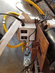
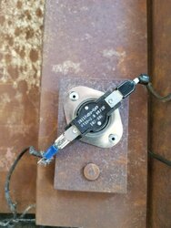
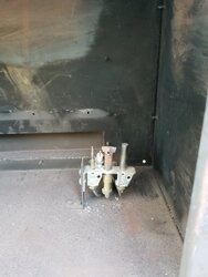
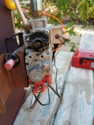
I have what looks similar to a Vermont Castings gas fired faux wood stove. It was used, minus manual, and worked well for a year. Then it started to go black inside from soot, and finally would just shut off after about ten minutes. It has a "T" shaped pilot light, the base of the vertical part of the T goes out over the main gas channel, the top of the T goes Left and Right, one to a thermopile (with copper pipe back to regulator) and the other to a thermocouple with two lead electric going to the electric block on the regulator.
Cleaned everything, including the thermcouple/thermopile, but still just shuts off after few minutes.
Any ideas why??
thanks
 
First of all, the ThermoCOUPLE is the smaller of the two & has a copper connection INTO the valve.
The ThermoPILE is larger & has the two wire connector to the terminal block of the valve.
If the unit is sooting, the air shutter - think air-to-fuel mixture - is closed too much.
What fuel are you burning? LP or NG? The ATF is different for each fuel...
When the unit shuts off, does the pilot stay lit?
Have you taken any milliVolt readings on the thermopile?
If so, what did you get?

THANK YOU for replying! Right, I will remember to identify which correctly. We are using NG, and I am pretty sure that is the correct one for this orifice, which I will go measure. I did open the air inlet on the gas burner pipe which fits over the orifice, and it reduced the amount of the yellow in the flames. But when testing the stove, after cleaning the thermocouple and thermopile, it still shut off after a few minutes, and both the main gas feed and the pilot gas feed shut down.
I am not sure how/where to measure the millivolt readings, but will do so if you can tell me or direct me to directions to do so.

Again, thank you. Out here, all the fireplace shops/dealers will have nothing to do with any product not sold directly by them.
spg
 

Attachments

  • gas stove pilot et al.jpg
    gas stove pilot et al.jpg
    83.3 KB · Views: 259
  • gas stove robertshaw reg 7000 series hydraulic.jpg
    gas stove robertshaw reg 7000 series hydraulic.jpg
    114.8 KB · Views: 291
You will need a multimeter set to Volts DC, with 2 probes.
Light the pilot.
Place the end of one probe on the screw at the RED terminal block (pic #2) marked TP - upper left.
Place the end of the other probe on the TH-TP screw head - bottom center.
Read the milliVolts on the meter. With the pilot burning, the mV should be in the 475 - 550 range.
Turn the burner on.
Read the milliVolts. They'll drop, but should be stable at about 190 - 220mV.
Let us know how you make out & we'll take it to the next step.


So I did the measurements as instructed, and it appears the first measured between 400-450; and then when I turned the burner on it dropped to 100-120. That is right, correct?
 
You will need a multimeter set to Volts DC, with 2 probes.
Light the pilot.
Place the end of one probe on the screw at the RED terminal block (pic #2) marked TP - upper left.
Place the end of the other probe on the TH-TP screw head - bottom center.
Read the milliVolts on the meter. With the pilot burning, the mV should be in the 475 - 550 range.
Turn the burner on.
Read the milliVolts. They'll drop, but should be stable at about 190 - 220mV.
Let us know how you make out & we'll take it to the next step.
 

Attachments

  • 20180220_142439.jpg
    20180220_142439.jpg
    64.6 KB · Views: 215
  • 20180220_143043.jpg
    20180220_143043.jpg
    61.7 KB · Views: 219
Yeah...Not good...Sounds like you need to replace the Thermopile...
About $50 for one called a universal MilliVolt Generator at True Value.
 
Wow, after 25 years servicing gas equipment I never asked anyone where they bought an appliance, I was just there to fix it !

DAKSY will be along to help you out, so I'll try not to confuse you or get in his way ;em. Your reading with pilot lit only is the no load voltage being generated by the Thermopile. That current is used to open the burner valve with a electromagnet in the valve, so with it on, you're reading the voltage drop from the current being used through the coil that makes the magnet. (as well as wiring and thermostat if wired to open gas valve) Since the pilot goes out as well, that is the current from the thermocouple that holds the safety valve open when heated by the pilot flame. Make sure when the main burner is lit the pilot is still strong engulfing about the top 1/3 of the thermocouple. A weak pilot can be thrown off course and not continue to heat the thermocouple properly. Voltage generated by thermocouple energizes an electromaget coil that holds the safety open. (what you hold in when lighting until it is generating enough current so the magnet holds it open for you when you let go)

Is this connected to a proper vent of the correct height? Most will have a large air intake at the bottom of exhaust vent called a diverter. It allows cool air up the pipe to cool and slow the draft. It should have a safety switch in the indoor airflow stream that is a temperature switch used as a exhaust spillage switch. It is designed to shut the gas off coming in the valve by breaking the current flow from thermocouple to valve. Make sure all heated exhaust is rising up the stack and not spilling out at the diverter. This safety switch is designed to heat the spillage switch when not drafting properly and shut the unit down like you're describing.

A simple test is to light the main burner and shake out a match to watch the smoke rush into diverter and up the stack. It shouldn't linger and stay in the building. When a main burner is first lit with a cold stack some spillage is normal until it heats the stack and starts drafting. That doesn't explain why it worked for a year unless something has changed with the venting system.
 
He beat me to it.
DAKSY, are you sure the thermopile holds the safety open? Sounds like the safety valve is shutting down and the thermopile should only operate the main burner??
Difficult not being there looking at the wiring.
Easy way to tell is remove one of the wires from thermopile and the safety should still hold pilot on. If it does, thermopile only works main gas valve. Obviously the main burner will not light with wire removed.
 
Last edited:
You stated when it shuts down the pilot goes out. That should have nothing to do with the thermopile. You can check it easily by removing one of the wires on the gas valve from thermopile. If pilot stays lit, the thermocouple is generating the power to hold safety open. I believe your thermopile only supplies power for the main burner. If the pilot goes out when the problem occurs it is due to the pilot safety system. (safety stops all gas flow through gas valve) The thermopile failure will only prevent the main burner from lighting. (the pilot would stay lit)
Do you know the make and model so we can look at a schematic before you spend $50 for a part you may not need?
 
Last edited:
I missed the pilot also extinguishing, but the mV on the thermopile is WAY TOO low.
Like you said, not being there makes it a little hard to diagnose.
To the OP is the unit a DV - pipe within a pipe, or is it a B-Vent - single 4" diameter pipe?
 
Last edited:
  • Like
Reactions: coaly
But we don't know how long it was lit before testing. I've seen some take quite a while to creep up and be up to 750 mv after five or ten minutes.
Then we don't know how long the thermostat wires could be, measuring the voltage drop not only from coil but through wires and switch points....... AND we're not looking at the strength of his pilot. Nothing like being there.
 
so sorry to have dropped out. had a 16 hour work day yesterday, and another tomorrow. but will try to put a more coherent package of data together, including a schemata of the wiring, pictures of all relevant items (What I think are relevant, but I am not that knowledgeable, obviously). It is hard working on an appliance that has no name plate, serial number, nada. Only stickers are some traditional warnings, and one Made In Canada label, but no Branding. And of course, no manual. However, I know it is not a cheap knock off, if a knock off at all. Please hang in there until I get the info better organized.

I really appreciate all your help. I've never used a forum, and find it, actually, exciting.

thank you,
steven
 
  • Like
Reactions: DAKSY
Hello again. Already pictured above is are shots of: gas valve; pilot carriage with the thermopile and thermocouple and pilot gas line and ignitor;
Also, a shot of the gas orifice. We have been using NG and it worked fine for one season, then the sooting and shutting off started.

Give the size of the orifice, I am pretty sure it is for NG; sadly, no markings on the gas valve can be found. Although when one looks at the robertshaw 710 series installation data sheet it appears my valve has a regulator conversion kit 1751-007. I will post the pdf for that sheet.

also, I will post my verbal schemata of the wiring for the unit. if needs be I could try to diagram it. but it is pretty straightforward.

finally I will post some more pictures of various aspects of the unit. I know it must be direct vented, and sealed (as per a label on the back), and the equipment we used was supplied by a stove store, so I have assumed it is correct. But,....?
 

Attachments

  • Robertshaw 710 series regulator.pdf
    1.4 MB · Views: 301
here is the verbal wiring info:

There is a thin metal cover plate over the back of the stove, sitting above the blower fan (which is a two unit system)

The blower fan has a standard 110 v polarity two plug (i.e. no ground) lead that plugs into a 110 v single gang box with two receptacles.

One of thess receptacles is hot wired that is, if you plug the fan into it, it turns on, and only turns off if it is unplugged ( and indeed upon inspection this receptacle is directly wired to the incoming supply (both hot and common);
the other is not hot wired (would assume the other is driven by the thermostat, and in fact the "hot" side of this receptacle comes from the round sensor device's blue clip side, while the common goes to the general common wire nut inside the gang box?) The box has a incoming standard polarity two plug line that goes to the wall of the room.

There is an ON/OFF rocker switch at the top of the cover plate. And a circular dial with white line on top mounted somewhat below it;
both easily accessible by reaching around the side of the stove. The circular dial turns on with a click and can rotate about 3/4 of a circle, and turns off with click without further rotation.

On the inside of the cover plate near the bottom, there is a flat round device (see pictures) which I assume is some form of sensor (?heat).

WIRING
All wires are heavy coated, presumably for protection from heat.

A black wire goes from the "ON" switch terminal to gas valve Red Terminal TH screw.
TP

A black wire goes from the "OFF" switch terminal to gas valve Red Terminal TH screw.

The wire two lead wire coming from the Thermopile goes to Red Terminal and one lead shares the TH screw,
TP

The other white lead goes solo to the TP screw.

There is an orange wire connecting the piezoelectric device from push button at the gas valve, to discharge unit at pilot carriage.

The black dial with white line on top has a black wire goes into the 110 volt single gang box and joins the other wires under the hot incoming lead wire nut.

The hot incoming lead wire nut feeds the always hot receptacle too. The common incoming lead feeds both receptacles.

The other side of the black dial has a black wire that goes into the black round sensor device, while the other side of that device has
a black wire (blue tipped) that goes to the 110 volt single box and is the sensor controlled hot side of the sometimes hot receptacle.

PILOT CARRIAGE
The pilot gas tube runs form the pilot outlet above the inlet wrench boss on the gas valve to the pilot outlet burn point, shooting
a flame up against a metal diversion hood, which shoots the flame left to the thermocouple, and right to the thermopile, as well
as forward over the main burner tube.

The thermopile has the white two lead wires coming from the bottom of it, and goes as noted above.

The thermocouple copper tube comes from the gas valve thermocouple inlet and goes to the pilot carriage.
 
***On the inside of the cover plate near the bottom, there is a flat round device (see pictures) which I assume is some form of sensor (?heat).***

I don't see that in any of the pix...

I'll ask again - Is this a Direct Vent or a B-Vent unit?
 
All 100 V is for the blower. The gas valve is a millivolt style. One recept. is controlled by the thermostat switch called a thermo-disc switch. It will have markings of F for Fan and temperaturefor on and off. a switch with F is normally OFF and turns ON with temperature rise. The blower should only run when the stove is hot plugged into the other recept. This has nothing to do with the unit shutting down.

Need to see the switch in air intake of divertor hood. (If it is what you describe at bottom of plate) If you can see it, see if there is a L on it with numbers. That stands for Limit. If so, it is normally ON until hot when it shuts OFF. That is the spillage switch to shut it down when not drafting correctly. Follow the wires from that switch and see if they go to the gas valve where the metal line connects from thermocouple. You can test to see if that is the spillage switch by removing one wire from it, and try to light pilot. It should light and go out when you release pilot knob. That will tell us if it is the pilot safety spillage switch.

Direct Vent means the heater gets combustion air from outside and the exhaust will be double wall with hot exhaust escaping from the center and cold intake air coming in the outer chamber. B-vent is a twist type lock together pipe with only hot exhaust flowing up through it above roof line.
 
  • Like
Reactions: DAKSY
sorry about pictures. am having trouble getting them from phone to computer. and can't address that today (16+ hour work day, but then have some days off).
it is a direct vent for sure. also, I don't follow everything coaly is saying. but will get the pics out tomorrow (got to, it's cold here right now )

thank you
 

Attachments

  • gas stove BOTTOM.jpg
    gas stove BOTTOM.jpg
    114.2 KB · Views: 248
  • gas stove heat sensor device 2.jpg
    gas stove heat sensor device 2.jpg
    112.6 KB · Views: 253
  • gas stove on off and dial switches 2.jpg
    gas stove on off and dial switches 2.jpg
    98.7 KB · Views: 179
FYI: THE only wires to/from the gas valve are those as stated in my written wiring schemata pdf above. There are none from one part of gas valve into another part.

spg
 
Notice the F on the switch you pictured. That is the FAN switch as I stated above. All that wiring outside of the burner area is 100 volt for the blower.

What makes the parts work that are causing the problem of shutting down is the thermocouple circuit.

When you light the pilot, one of the pilot flames heats the smaller of the two "generators". (that is the thermocouple) Inside that small tube the flame should cut across (thermocouple tip) is a piece of metal that bends when hot against another dissimilar metal contact inside. This generates a small electrical current inside a conductor which is inside the metal tube which is the "power" feed from thermocouple to gas valve. When you light the pilot, you have to press the pilot knob IN to open the valve that allows gas to flow through the valve. While holding it in, the heat from pilot flame bends the contacts together in thermocouple which creates enough current to energize a electromagent in valve. This magnet then holds the valve open for you when you let go. (a steel rod you were holding against spring pressure)
As long as the correct heat is being supplied the gas valve remains open allowing gas to flow. If anything causes a drop in voltage to valve, it closes with a click and shuts gas off through valve. This is what is happening when it shuts down.

If you don't understand that, go no farther and ask.

If this appliance were a normally vented gas stove that used INDOOR air for combustion, it would have a safety switch on the thermocouple line (the switch with "L" for Limit) in the air intake for the exhaust flow. This is to shut the valve off in case of CO leakage into home. You don't have that on direct vented unit since there is no communication with indoor air and the burner.

Since your problem is after 10 minutes of operation, is that 10 minutes of main burner operation, or does it go out if only the pilot is lit for a period of time as well? In other words, if you only light the pilot and leave control in pilot position, does it remain lit ??
 
  • Like
Reactions: DAKSY
Notice the F on the switch you pictured. That is the FAN switch as I stated above. All that wiring outside of the burner area is 100 volt for the blower.

What makes the parts work that are causing the problem of shutting down is the thermocouple circuit.

When you light the pilot, one of the pilot flames heats the smaller of the two "generators". (that is the thermocouple) Inside that small tube the flame should cut across (thermocouple tip) is a piece of metal that bends when hot against another dissimilar metal contact inside. This generates a small electrical current inside a conductor which is inside the metal tube which is the "power" feed from thermocouple to gas valve. When you light the pilot, you have to press the pilot knob IN to open the valve that allows gas to flow through the valve. While holding it in, the heat from pilot flame bends the contacts together in thermocouple which creates enough current to energize a electromagent in valve. This magnet then holds the valve open for you when you let go. (a steel rod you were holding against spring pressure)
As long as the correct heat is being supplied the gas valve remains open allowing gas to flow. If anything causes a drop in voltage to valve, teat closes with a click and shuts gas off through valve. This is what is happening when it shuts down.

If you don't understand that, go no farther and ask.

If this appliance were a normally vented gas stove that used INDOOR air for combustion, it would have a safety switch on the thermocouple line (the switch with "L" for Limit) in the air intake for the exhaust flow. This is to shut the valve off in case of CO leakage into home. You don't have that on direct vented unit since there is no communication with indoor air and the burner.

Since your problem is after 10 minutes of operation, is that 10 minutes of main burner operation, or does it go out if only the pilot is lit for a period of time as well? In other words, if you only light the pilot and leave control in pilot position, does it remain lit ??
I do understand what you wrote, thank you for being so detailed.
Re when does the stove shut off, I wanted to test that, so I lit the pilot, and no more. The pilot stayed lit for two days. Then, when I flipped the switch to on, the burner immediately lit. However, in about two minutes now, it shut down the whole pilot system, i.e. the burner went off, the pilot lite went off.

NOW, one more variable. The dial on the gas valve, a metal dial with lo --- hi stamped on it, and is more centered next to the black plastic gas valve dial that is held in to start the pilot. That metal dial spins freely, meaning the plunger button inside the dial is moved either in or out.
Is this contributing to the problem too?

Do you agree the orifice is indeed for NG?

thanks

steven