Evaluate my piping diagram

  • Active since 1995, Hearth.com is THE place on the internet for free information and advice about wood stoves, pellet stoves and other energy saving equipment.

    We strive to provide opinions, articles, discussions and history related to Hearth Products and in a more general sense, energy issues.

    We promote the EFFICIENT, RESPONSIBLE, CLEAN and SAFE use of all fuels, whether renewable or fossil.
Status
Not open for further replies.

Clarkbug

Minister of Fire
Dec 20, 2010
1,273
Upstate NY
Hello All!

I see your wisdom, and general comments, on my proposed piping schematic for my Varmebaronen install.

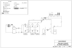
Thanks to skfire from this site, I had a great head start on a schematic. Its based on the Tarm diagrams, tweaked to fit my existing system. The intent is to hook up two zones with capped connections for two future ones, one for heat, one for DHW.

Control will be through the BLT control box tied into my existing Taco zone control.

Im specifically looking to see if anyone thinks I can add/delete any ball valves, drains, temp gauges, etc. Also thinking the expansion tank should be connected to the air scoop, or off of the bottom connection to the tanks. Also need to size the expansion tank, but Im thinking I probably need two of them now....

Im also curious about where the best place for me to measure tank temps would be, or if I need to measure all three tanks, etc.

Thanks in advance.
 

Attachments

  • Vedolux37PipingSchematicWEB.jpg
    Vedolux37PipingSchematicWEB.jpg
    46.3 KB · Views: 886
Clarkbug said:
Also thinking the expansion tank should be connected to the air scoop, or off of the bottom connection to the tanks. Also need to size the expansion tank, but Im thinking I probably need two of them now....

Usually there are two expansion tanks in this type of system. ZV-1 and the diverting valve can isolate the oil boiler/load side so a small expansion tank conventionally placed on the OB air separator would take care of that.

The main expansion tank can be tied-in most anywhere on the storage tank/wood boiler side, as long as air can't migrate into the water side of the diaphragm, which just means the piping needs to go continuously downhill from the point it is tied-in to the system. Some will insist that you need to pump away from the point of zero pressure change as if it failing to do so would touch some third rail of hydronic plumbing, but with all that 1.5" pipe going to and from storage 'pumping away' is not a valid concern on the wood boiler/storage side.

As far as expansion tank size, short answer is 10% of system volume for a diaphragm expansion tank.

I don't know why anyone would connect to storage a sixth of the way away from the top and bottom. If it's absolutely necessary, as someone suggested in a previous thread you could consider an internal dip tube to the bottom of the tank and a riser tube to the top as well in order to use all the storage you've paid for.
 
Thanks Eliot.

You made me realize that I forgot to show the other expansion tank. There appears to be a small diaphragm type on the boiler, as well as a very old one that is hiding up in the rafters near the boiler. Im guessing thats just half filled with water, half with air. Ill try to add that back into my diagram later today while Im thinking about it.

I like the 10% answer. I started trying to do the calcs per the Amtrol literature and started seeing dollar signs add up quickly (OK, more quickly than they have so far).

Im going to have to find some of those double threaded bushings to make the dip tubes I think. Im limited to using the existing tappings on the tanks (or I guess I should say I am limiting myself to using the existing tappings on the tanks), so that leaves me 13" from either end for inlet/outlet. Since the taps on the tanks are 1 1/2" and Im going to run 1 1/4" between all of them, it shouldnt be a problem to neck down to a 1" inside the tank for a dip tube, correct? Im thinking I can mess around with some copper to get them put together this week. Or Ill have to see if I have any black iron around, but I would think that may be harder to get inside the tank with an elbow on it.
 
The way your diagram has the tankes plumbed I don't think they will charge evenly. If going parallel you need the same amount of pipe going to each tank. With three tanks I'd probably go in series. Just my 2 cents.
 
woodsmaster said:
The way your diagram has the tanks plumbed I don't think they will charge evenly. If going parallel you need the same amount of pipe going to each tank. ...

It's drawn as a 'reverse return' configuration, so the longer path on one end is balanced by a shorter path on the other end, so it works out pretty slick.

--ewd
 
ewdudley said:
woodsmaster said:
The way your diagram has the tanks plumbed I don't think they will charge evenly. If going parallel you need the same amount of pipe going to each tank. ...

It's drawn as a 'reverse return' configuration, so the longer path on one end is balanced by a shorter path on the other end, so it works out pretty slick.

--ewd

I see !
 
Clarkbug said:
I like the 10% answer. I started trying to do the calcs per the Amtrol literature and started seeing dollar signs add up quickly (OK, more quickly than they have so far).
Amtrol's worksheets should come out about the same unless there is something special about your system.
Im going to have to find some of those double threaded bushings to make the dip tubes I think. Im limited to using the existing tappings on the tanks (or I guess I should say I am limiting myself to using the existing tappings on the tanks), so that leaves me 13" from either end for inlet/outlet. Since the taps on the tanks are 1 1/2" and Im going to run 1 1/4" between all of them, it shouldnt be a problem to neck down to a 1" inside the tank for a dip tube, correct? Im thinking I can mess around with some copper to get them put together this week. Or Ill have to see if I have any black iron around, but I would think that may be harder to get inside the tank with an elbow on it.

Just a copper 45 degree elbow with a piece of pipe that heads off towards the top/bottom should do the trick, you're just looking to pick up a few inches on each end to reclaim a fair amount of the dead space in each end. Or maybe heat and bend a piece of 1" black iron, the kinks wouldn't amount to much for as much flow will be going through each of the three legs. Just need to mark the bushing on the outside so you can end up pointing the right direction.

1" should be plenty with the flow split three ways. 20 gpm works out to 2.76 feet per second when split three ways through 1" pipe. Also at the end of the burn when storage is hot and flow from the boiler is maximum, then jetting turbulence into the tops of the tanks matters not at all.

--ewd
 
The biggest thing that I see is that the T&P relief valve that ships with the boiler doesnt go up to 30 PSI, instead its 1.5 bar, or about 22 psi. So that adds to the tank size according to the calcs.

I appreciate your comments, and willingness to take a look at this stuff! It definitely helps out.
 
ewdudley said:
Just a copper 45 degree elbow with a piece of pipe that heads off towards the top/bottom should do the trick, you're just looking to pick up a few inches on each end to reclaim a fair amount of the dead space in each end. Or maybe heat and bend a piece of 1" black iron, the kinks wouldn't amount to much for as much flow will be going through each of the three legs. Just need to mark the bushing on the outside so you can end up pointing the right direction.

1" should be plenty with the flow split three ways. 20 gpm works out to 2.76 feet per second when split three ways through 1" pipe. Also at the end of the burn when storage is hot and flow from the boiler is maximum, then jetting turbulence into the tops of the tanks matters not at all.

--ewd

Any idea how much heat is needed to get the iron pipe to bend? Im pricing out the fittings I would need (Its never good when FW Webb doesnt have some of the ones you want...) and to do this in copper would be somewhere around $120. Ill do it if I have to, but cranking on a 12" pipe nipple thats been heated is much more appealing to me from a cost standpoint...
 
Clarkbug said:
Any idea how much heat is needed to get the iron pipe to bend? Im pricing out the fittings I would need (Its never good when FW Webb doesnt have some of the ones you want...) and to do this in copper would be somewhere around $120. Ill do it if I have to, but cranking on a 12" pipe nipple thats been heated is much more appealing to me from a cost standpoint...

You can bend it cold if can get one end anchored without buggering the threads too much, it's just that heating it to full cherry (1500 degF) would make it easier, more fun, and prettier. But kinks and not being pretty won't matter where it's going, so have at it! Or find a pro who does race car roll cages and such and have it done right. Also you may be able to find some thinner wall conduit, fire sprinkler pipe, or some such that would be easier to work with.

The biggest thing that I see is that the T&P relief valve that ships with the boiler doesnt go up to 30 PSI, instead its 1.5 bar, or about 22 psi. So that adds to the tank size according to the calcs.
Bummer, that's a real deficiency on Varmbaronen's part, I'd say, although I still really like the looks of them. Still the 86 gallon Amtrol tank might well do the trick if you don't push way up over 190 degF.
 
Perhaps Ill just get some pipe caps to save the threads and see what I can do with a really big wrench/hammer over the weekend. Certainly would be cheaper than the copper fittings route.

I was a little surprised to see that lower pressure rating as well, which is a downer for me. Just means a bigger expansion tank I suppose. It says the test pressure is 31 PSI, but Im going to use the T&P they sent over rather than risk anything (especially warranty). My whole house is baseboard, so Im going to try and push my temps up close to 200 if at all possible, just to maximize what I can for a burn/storage. So unless I can pre-heat all of the water as Im filling the system, Im worried that Ill have to buy a couple of expansion tanks and hook them up together.
 
Clarkbug said:
I was a little surprised to see that lower pressure rating as well, which is a downer for me. Just means a bigger expansion tank I suppose. It says the test pressure is 31 PSI, but Im going to use the T&P they sent over rather than risk anything (especially warranty). My whole house is baseboard, so Im going to try and push my temps up close to 200 if at all possible, just to maximize what I can for a burn/storage. So unless I can pre-heat all of the water as Im filling the system, Im worried that Ill have to buy a couple of expansion tanks and hook them up together.

If by some luck you could place your expansion tank in the attic or in an upstairs closet, you might be able to run the tank from 2, 3, or 4 psig to 12, 13, or 14 psig instead of from 12 psig to 22 psig at the lowest elevation, which would let you use a tank only 75% to 80% as big. You could run 3/8" oxygen barrier pex up to it, but you'd need to go up to a high point with an air bleeder and then back down to the tank to prevent any possibility of air accumulating on the water side of the bladder.
 
Unfortunately no such way to get a tank into the attic. Well, really not a good way to get the piping up there, and I dont want to fight the bats, so its gonna stick to the basement for now. I at least have the real estate for the expansion tanks, I just dont know if my wallet can handle them...

I also saw your message regarding the tempering valve in the Tarm diagram. I do intend to use a lower temp valve than the one they suggest, just to try and help stretch my storage out some. I found that there is a US manufacturer that makes the tempering valves also that may be less expensive, but Im not positive on that one yet. I need to try and find one of these valves for sale, since I dont see many on the net for some reason.
 
So an update on my expansion tank situation...

Unfortunately it looks like a bummer, at least to my wallet. Having a max system pressure of 22 PSI really did put a limit to things. But, I was able to use the Amtrol calculator, and then I also found the Bell & Gossett technical guide for this sorta stuff, and the numbers were close enough for me. What it works out to is that I need 3 of the SX-60V expansion tanks manifolded together. This seemed to be the best "bang for the buck" combination of tanks based on the pricing from some of the online vendors. This assumes that I can turn down the fill pressure of the system to the 10 PSI listed on my fill valve. Im sure Im a little conservative, but I dont think there is much more I can shave off from it.
 
Status
Not open for further replies.