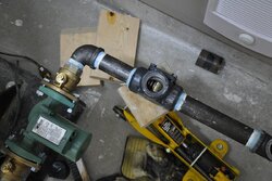
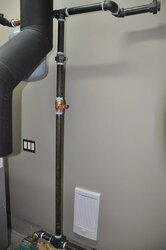
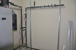
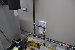
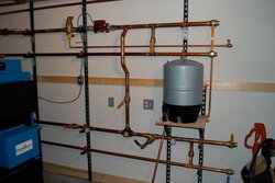
Ive been looking at few pics of various near boiler piping configurations and noticed some have the bypass valve on the vertical section of pipe above the danfoss and some have it on the bypass piping to the cool water return. Does this matter. or what is the preferable method.
Huff
Huff
 ! I now have a warm barn so I dont need this feature anymore but ya never know!