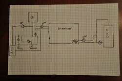
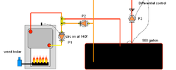
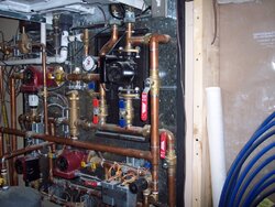
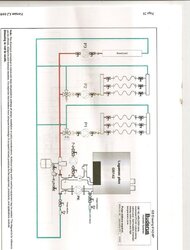
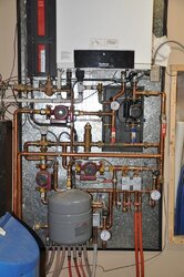
This is how I ran my system last year. Ignore the large tank, consider that your primary loop.
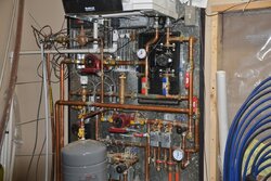
I repiped recently when that buffer/ separator tank came my way. The only issue with last years piping was the need to heat the 500 gallons before I could move energy to the radiant. Now the EKO heats that 50 gallon buffer in 15 minutes or so even from a cold 60F start up. On mild days i don't need to heat the 500 gallons, build a small fire and transfer directly to the load.
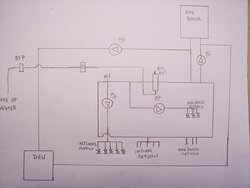
With this piping you have a few choices. The EKO has the ability to run the boiler pump. Mine would turn on at @ 155F and off @ 140F. At least that is how my 2005 version EKO 40 is setup.
That really does a adequate job of boiler return protection without needing that 3 way thermostatic valve. No need to balance and mess with a 3 way, and they do use a small amount of your pumping head. It does so by switching the pump on and off a bit until the boiler hits it's stride. that cycling is the only drawback to a bang/ bang control.
As a second level of protection I ran that circ on the cross over as a delta t with variable speed. So as the boiler hits say 155f that circ kicks on at 100% speed. After 20 seconds it drops to 30% (adjustable) speed. For every 10 degrees the boiler temperature rises (adjustable) the pump speeds up one step. So it moves the amount of energy the boiler is producing, exactly.
The pumps can be any size, (1 amp or less) off the shelf wet rotor. Taco, Grundfos, Wilo, B&G your choice. Size the pumps to the load they are moving. I suspect a Grundfos 15-58 on speed two will cover your application. The control will vary the speed as needed, a fixed speed Grundfos 15-42 might be even cheaper to purchase..
I'll bet you can find a dual output solar control online for about the same $$ as a large thermostatic, and now you have two functions covered with some energy monitoring functions also.
OR both the boiler pump, and the crossover pump could run off the dual output solar control. Both on a variable speed function. Set the boiler pump to fire on when the boiler reaches a min. temperature, 155F works for me. With both pumps working off a delta T AND variable speed you are always moving the energy around at the exact rate needed and with the least amount of electrical energy. No need to use an Alpha here, save it for the zone distribution circ where it can use it's intelligence wisely.
hr