
Last year I purchased a Jotul C350 fireplace insert. I'm having this installed in a cabin with an old brick chimney that is about 17 feet tall. The company I hired installed a 5" insulated liner, but the fireplace insert collar is 6". Some initial searching suggests this is a bad idea, as this reduces the cross section area by 30%. Are there any conditions where a 5" flue will be adequate?
Jotul C350 with a 5" liner
- Thread starter riverfire
- Start date
-
Active since 1995, Hearth.com is THE place on the internet for free information and advice about wood stoves, pellet stoves and other energy saving equipment.
We strive to provide opinions, articles, discussions and history related to Hearth Products and in a more general sense, energy issues.
We promote the EFFICIENT, RESPONSIBLE, CLEAN and SAFE use of all fuels, whether renewable or fossil.
You are using an out of date browser. It may not display this or other websites correctly.
You should upgrade or use an alternative browser.
You should upgrade or use an alternative browser.
Maybe with a 35' flue. All you can do at this point is try it and see how it performs. Or reject the job and halt payment if the contract specified 6". Do you know the chimney ID?
I don't know the exact ID, but I see the insulated liner was a very tight fit through the damper. I believe it is fine above that. A larger size may take more work. I see some people use a sawzall on the damper plates or use an oval flue to work around bottlenecks. Perhaps a 6 inch liner without insulation would be similar in outer diameter. Due to damper location, the insert is also currently offset 8 inches back from the front of the fireplace, and will require some kind of angle adapter to make the plates flush with the surround. My concern is that both the angle adapter and the smaller liner size will reduce draft. Does this just reduce efficiency or are there other concerns going with a smaller size?
Last edited:
One thing I’d be curious about is if they used any sort of adaptor from 6in to 5 in. The “draw down adaptor“ provided with Jotul inserts ( the stainless piece that fits into stove collar and then liner fits into adapter)is 6 in to match the stove collar. Hopefully they did not provide you a leaky set up. Pics may help. The cast surround is heavy but pretty straightforward to remove. Putting it back in place takes some practice .
I believe there is an adapter (second part below). The packing slip lists the following:
L525IK-B6
LW 5" IDX25' INSERTKIT 304-006 -- ITEM COMPONENTS INCLUDE: TPCC5SQL-B, TPC5-1313-B, NO ADAPTER, BOX
IR65-B
6" - 5" INC/RED (3PC) 304
Here are some photos of the installation in progress that show the issues.
Due to the damper/liner position and the collar on the insert, the unit is currently set back 8 inches with respect to the surround bricks. It will need an angle adapter of some sort in order for the surround panels to mount flush with the fireplace.
![[Hearth.com] Jotul C350 with a 5" liner](https://www.hearth.com/talk/attachments/img_2626-webp.262684/ "[Hearth.com] Jotul C350 with a 5\" liner")
![[Hearth.com] Jotul C350 with a 5" liner](https://www.hearth.com/talk/attachments/img_2637-webp.262686/ "[Hearth.com] Jotul C350 with a 5\" liner")
![[Hearth.com] Jotul C350 with a 5" liner](https://www.hearth.com/talk/attachments/img_2627-webp.262687/ "[Hearth.com] Jotul C350 with a 5\" liner")
![[Hearth.com] Jotul C350 with a 5" liner](https://www.hearth.com/talk/attachments/img_2638-webp.262688/ "[Hearth.com] Jotul C350 with a 5\" liner")
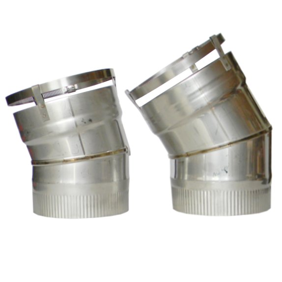
One of these adapters may be needed. If there is space for the first one, I would assume that has less impact on draft.
![[Hearth.com] Jotul C350 with a 5" liner](https://www.hearth.com/talk/data/attachments/71/71705-6074cd430fb03a8c3faa71cfb7d9c564.jpg "[Hearth.com] Jotul C350 with a 5\" liner") (broken image removed)
(broken image removed)
I won't be able to install the cast iron surround plates until the unit is flush the with surround bricks. In the photos above the clamps and ratchet strap are an attempt to re-attach the front plate (I removed it to transport the unit in pieces by canoe).
Here is a look up the chimney with the sealing plates installed. Cutting a semi-circle in the the rusty iron damper would be arduous, but might buy more room for the installation.
![[Hearth.com] Jotul C350 with a 5" liner](https://www.hearth.com/talk/attachments/img_2642-webp.262689/ "[Hearth.com] Jotul C350 with a 5\" liner")
![[Hearth.com] Jotul C350 with a 5" liner](https://www.hearth.com/talk/attachments/img_2643-webp.262690/ "[Hearth.com] Jotul C350 with a 5\" liner")
Here is a look up the chimney without the plates from the left, center and right side.
![[Hearth.com] Jotul C350 with a 5" liner](https://www.hearth.com/talk/attachments/img_2646-webp.262691/ "[Hearth.com] Jotul C350 with a 5\" liner")
![[Hearth.com] Jotul C350 with a 5" liner](https://www.hearth.com/talk/attachments/img_2657-webp.262692/ "[Hearth.com] Jotul C350 with a 5\" liner")
![[Hearth.com] Jotul C350 with a 5" liner](https://www.hearth.com/talk/attachments/img_2654-webp.262693/ "[Hearth.com] Jotul C350 with a 5\" liner")
Here is a close up of the junction between the 6" - 5" adapter and the insulated liner.
![[Hearth.com] Jotul C350 with a 5" liner](https://www.hearth.com/talk/attachments/img_2659-webp.262694/ "[Hearth.com] Jotul C350 with a 5\" liner")
The upper chimney outer dimensions are 18" x 22".
![[Hearth.com] Jotul C350 with a 5" liner](https://www.hearth.com/talk/data/attachments/262/262725-7df9a9da8075885c9f51356ba2f6fd36.jpg?hash=9zNL2U30At "[Hearth.com] Jotul C350 with a 5\" liner")
L525IK-B6
LW 5" IDX25' INSERTKIT 304-006 -- ITEM COMPONENTS INCLUDE: TPCC5SQL-B, TPC5-1313-B, NO ADAPTER, BOX
IR65-B
6" - 5" INC/RED (3PC) 304
Here are some photos of the installation in progress that show the issues.
Due to the damper/liner position and the collar on the insert, the unit is currently set back 8 inches with respect to the surround bricks. It will need an angle adapter of some sort in order for the surround panels to mount flush with the fireplace.
One of these adapters may be needed. If there is space for the first one, I would assume that has less impact on draft.
I won't be able to install the cast iron surround plates until the unit is flush the with surround bricks. In the photos above the clamps and ratchet strap are an attempt to re-attach the front plate (I removed it to transport the unit in pieces by canoe).
Here is a look up the chimney with the sealing plates installed. Cutting a semi-circle in the the rusty iron damper would be arduous, but might buy more room for the installation.
Here is a look up the chimney without the plates from the left, center and right side.
Here is a close up of the junction between the 6" - 5" adapter and the insulated liner.
The upper chimney outer dimensions are 18" x 22".
Attachments
![[Hearth.com] Jotul C350 with a 5" liner](/talk/data/attachments/262/262712-a14611ec143d12d87053efa5d518489c.jpg?hash=V0zmfUgNzE)
Last edited by a moderator:
Typically the damper area is cut out or notched to clear the liner. If there was plenty of room in the flue for a 6" liner then this should have been done. An angle grinder and sometimes a Sawzall are used to do this. The chimney looks to be just at the minimum height. I would not downsize in this case. Try to determine the flue tile size.
From the manual:
A 6”, 7”, or 8” stainless steel liner, extending the full height of the chimney, is required for all installations where the flue tile is greater than 8” x 12” for internal chimneys, or 9” x 8” for external chimneys.
Is that metal tape on the flue collar? Is that stainless steel pipe used a the offset? Can you post a larger sized image of this shot? Or a closer shot of the liner connection to the stove up to the damper?
![[Hearth.com] Jotul C350 with a 5" liner](https://www.hearth.com/talk/data/attachments/262/262727-de7b85f9f747266decff7bc24e8fd2d5.jpg?hash=iR2crcI3DC "[Hearth.com] Jotul C350 with a 5\" liner")
An offset composed out of 2 elbows is much more preferred to an offset box. SS elbows come in 15º, 30º and 45º angles. If the damper is notched to clear the 6" liner, it can be curved toward the front after clearing the damper and then only a single elbow (with liner clamp) is needed to connect the stove.
 www.rockfordchimneysupply.com
From the manual:
A 6”, 7”, or 8” stainless steel liner, extending the full height of the chimney, is required for all installations where the flue tile is greater than 8” x 12” for internal chimneys, or 9” x 8” for external chimneys.
Is that metal tape on the flue collar? Is that stainless steel pipe used a the offset? Can you post a larger sized image of this shot? Or a closer shot of the liner connection to the stove up to the damper?
An offset composed out of 2 elbows is much more preferred to an offset box. SS elbows come in 15º, 30º and 45º angles. If the damper is notched to clear the 6" liner, it can be curved toward the front after clearing the damper and then only a single elbow (with liner clamp) is needed to connect the stove.
Fixed Elbows for Stainless Steel Flexible Chimney Liners - Rockford Chimney
Our Chimney Liner Elbows have laser welded seams and feature the quick connect band clamp for a secure fit every time. Choose from 15 or 30 degree elbows.
www.rockfordchimneysupply.com
Last edited:
> Is that metal tape on the flue collar?
It is metal tape that has been spray painted black.
I included a picture of the metal tape below that includes the following text:
3M
11/20
3340
181 AP
181B-FX
Cold Weather
![[Hearth.com] Jotul C350 with a 5" liner](https://www.hearth.com/talk/data/attachments/262/262730-e249793ce1d1b3c5b25fb770882f463a.jpg?hash=I90r0uNN0Y "[Hearth.com] Jotul C350 with a 5\" liner")
> Is that stainless steel pipe used a the offset?
I believe the collar leads to this part # (New England Chimney Supply):
IR65-B
6" - 5" INC/RED (3PC) 304
Which then connects to the liner:
L525IK-B6
LW 5" IDX25' INSERTKIT 304-006 -- ITEM COMPONENTS INCLUDE: TPCC5SQL-B, TPC5-1313-B, NO ADAPTER, BOX
I assume it is stainless steel, but I will try to confirm this.
> Can you post a larger sized image of this shot? Or a closer shot of the liner connection to the stove up to the damper?
Please see below. Let me know if anything else would be helpful.
The tape around the collar was removed and the liner was lifted out slightly in preparation for a follow up angle adapter (or similar) to address the 8 inch offset.
![[Hearth.com] Jotul C350 with a 5" liner](https://www.hearth.com/talk/data/attachments/262/262728-305ad5ecccc2754579309b478fef58ca.jpg?hash=uFubJUMOHG "[Hearth.com] Jotul C350 with a 5\" liner")
![[Hearth.com] Jotul C350 with a 5" liner](https://www.hearth.com/talk/data/attachments/262/262729-943e269a0236aaacec5710faba772a2d.jpg?hash=HcKLJJe7NF "[Hearth.com] Jotul C350 with a 5\" liner")
Thanks for the follow up.
It is metal tape that has been spray painted black.
I included a picture of the metal tape below that includes the following text:
3M
11/20
3340
181 AP
181B-FX
Cold Weather
> Is that stainless steel pipe used a the offset?
I believe the collar leads to this part # (New England Chimney Supply):
IR65-B
6" - 5" INC/RED (3PC) 304
Which then connects to the liner:
L525IK-B6
LW 5" IDX25' INSERTKIT 304-006 -- ITEM COMPONENTS INCLUDE: TPCC5SQL-B, TPC5-1313-B, NO ADAPTER, BOX
I assume it is stainless steel, but I will try to confirm this.
> Can you post a larger sized image of this shot? Or a closer shot of the liner connection to the stove up to the damper?
Please see below. Let me know if anything else would be helpful.
The tape around the collar was removed and the liner was lifted out slightly in preparation for a follow up angle adapter (or similar) to address the 8 inch offset.
Thanks for the follow up.
Last edited:
I would not be happy at all with that installation. Not one bit.
Metal tape does not belong on a liner. It gets too hot. The tape rating is up to 300º. The liner will get over 800º at times. There will be no need for it with the proper fittings. Get a SS elbow with the proper liner clamp.
I appreciate the feedback. This is my first stove/insert, so I don't have much intuition for what the cumulative impact of changes such as elbows and diameter reductions will be on draft. If the consensus was "don't worry about it" for this unit + chimney height, I'd be inclined to try it. I have read enough posts of people struggling with draft due to setup that it sounds more like "worry about it" is the right impulse. I'm inclined to work towards removing the crown and liner and taking whatever steps are needed to put the 6 inch in place. Are the oval 6 inch equivalents suitable alternatives?
In some cases a 6" oval liner is an alternative. Knowing the current flue's ID will help with this decision and what the alternatives are.
> Knowing the current flue's ID will help with this decision
I will try to measure this, although it may be challenging in the current state due the cement crown on top and the tight fit of the liner itself through the damper on the bottom. If I get to the point where the liner is removed I can try to obtain measurements.
UPDATE: I've hauled the insert out of the firebox and should have enough clearance to provide the measurements you asked for. I'll follow up shortly.
Last edited:
> There’s a big gap where adaptor meets stove collar.
That particular photo is misleading. I should have commented on that. It wasn't left that way initially. The liner was detached from the fireplace insert (metal tape was removed and the beveled friction fit adapter was lifted up out of the collar an inch or so) once it became clear the surround plates couldn't be installed with this layout. An offset adapter of some sort was to be installed in a follow up visit.
That particular photo is misleading. I should have commented on that. It wasn't left that way initially. The liner was detached from the fireplace insert (metal tape was removed and the beveled friction fit adapter was lifted up out of the collar an inch or so) once it became clear the surround plates couldn't be installed with this layout. An offset adapter of some sort was to be installed in a follow up visit.
It belies other issues. You don't screw attach a liner to a fitting. They make liner clamping fittings for this purpose. See link posted earlier. The installer quite frankly seems a bit over his head.That particular photo is misleading. I should have commented on that. It wasn't left that way initially. The liner was detached from the fireplace insert (metal tape was removed and the beveled friction fit adapter was lifted up out of the collar an inch or so) once it became clear the surround plates couldn't be installed with this layout. An offset adapter of some sort was to be installed in a follow up visit.
I'm struggling a bit to get good photos with my head facing up the chimney while juggling a light, camera, and a tape measure. It is a good job for a 3D camera. Here is what I've managed to capture in 2D for the lower dimensions so far (near the damper).
The span from the lower rear to upper front pieces of the remaining damper construction shown below is about 7.5 inches. There is about a 6 inch vertical drop (Z axis) between the two points being measure. A photo below that shows about a 4 inch lateral (X-axis) offset between the pieces. There is a fair amount of free space above and behind the damper as shown to the right in this photo. As suggested above, it seems sawing this out would be possible and allow for a much straighter connection to the liner.
![[Hearth.com] Jotul C350 with a 5" liner](https://www.hearth.com/talk/data/attachments/262/262747-724c8b5855f550fdf212f71f56c3c5fe.jpg?hash=IkampxlNy6 "[Hearth.com] Jotul C350 with a 5\" liner")
![[Hearth.com] Jotul C350 with a 5" liner](https://www.hearth.com/talk/data/attachments/262/262748-7595a49397942455ec7c639e748ac626.jpg?hash=zBLqPzqGjw "[Hearth.com] Jotul C350 with a 5\" liner")
This shot is pointed straight up the chimney and shows the depth of each of the damper components. I
![[Hearth.com] Jotul C350 with a 5" liner](https://www.hearth.com/talk/data/attachments/262/262753-151119f5d8a9fb4627e0a46fd2ecbda5.jpg?hash=iETJ1svoWg "[Hearth.com] Jotul C350 with a 5\" liner")
This photo shows approximately 8 inches of "hidden space" above the damper, where the end of the tape measure is hitting the wall and the lip of the damper is at approximately the 8 inch mark. As shown in the earlier posts, the unit needs almost exactly 8 inches to make it flush with the outer fireplace bricks. Even if only 6 inches can be reclaimed here, that would leave a fairly gentle slope from the collar to the center of the chimney.
![[Hearth.com] Jotul C350 with a 5" liner](https://www.hearth.com/talk/data/attachments/262/262754-3f793da82ebd9177c545318554ce61a7.jpg?hash=bccM6QdTqe "[Hearth.com] Jotul C350 with a 5\" liner")
This panorama attempts to capture the horizontal span (I didn't have distance or FOV for a normal photo), at the widest part of the damper plates, which is roughly 30 inches:
![[Hearth.com] Jotul C350 with a 5" liner](https://www.hearth.com/talk/data/attachments/262/262749-a214088bf56c1544b7f6c0a2a0b5b780.jpg?hash=cSri9GJU94 "[Hearth.com] Jotul C350 with a 5\" liner")
![[Hearth.com] Jotul C350 with a 5" liner](https://www.hearth.com/talk/data/attachments/262/262751-b3794e96ee3a1a085a3848aa1bd08336.jpg?hash=LmvaP5vBdH "[Hearth.com] Jotul C350 with a 5\" liner")
It narrows in somewhat of an "S" configuration above this. This photo gives some indication of the construction above this and where they chiseled the rear masonry in the chimney to make space for the liner and the insulation "blanket". I believe the chiseling was only needed to curve around the damper plate.
![[Hearth.com] Jotul C350 with a 5" liner](https://www.hearth.com/talk/data/attachments/262/262750-77f965960cd1f39b5520f8ffbab4d185.jpg?hash=Inmx09bvrE "[Hearth.com] Jotul C350 with a 5\" liner")
I'm still trying to get measurements above this, but I believe there is plenty of space for a 6 inch insulated liner in the upper part if the proposed sawzall mod to the damper plate removed the need for the curve below. Hacking the masonry didn't appear to be necessary and now leaves it in a state where an angle offset adapter is required with some additional reduction in draft.
The span from the lower rear to upper front pieces of the remaining damper construction shown below is about 7.5 inches. There is about a 6 inch vertical drop (Z axis) between the two points being measure. A photo below that shows about a 4 inch lateral (X-axis) offset between the pieces. There is a fair amount of free space above and behind the damper as shown to the right in this photo. As suggested above, it seems sawing this out would be possible and allow for a much straighter connection to the liner.
This shot is pointed straight up the chimney and shows the depth of each of the damper components. I
This photo shows approximately 8 inches of "hidden space" above the damper, where the end of the tape measure is hitting the wall and the lip of the damper is at approximately the 8 inch mark. As shown in the earlier posts, the unit needs almost exactly 8 inches to make it flush with the outer fireplace bricks. Even if only 6 inches can be reclaimed here, that would leave a fairly gentle slope from the collar to the center of the chimney.
This panorama attempts to capture the horizontal span (I didn't have distance or FOV for a normal photo), at the widest part of the damper plates, which is roughly 30 inches:
It narrows in somewhat of an "S" configuration above this. This photo gives some indication of the construction above this and where they chiseled the rear masonry in the chimney to make space for the liner and the insulation "blanket". I believe the chiseling was only needed to curve around the damper plate.
I'm still trying to get measurements above this, but I believe there is plenty of space for a 6 inch insulated liner in the upper part if the proposed sawzall mod to the damper plate removed the need for the curve below. Hacking the masonry didn't appear to be necessary and now leaves it in a state where an angle offset adapter is required with some additional reduction in draft.
You’re going through a heck of a lot of trouble to figure this out. You paid a professional to do this for you. They gave you a chitty installation in my opinion. I’d demand the money back and then hire a better installer. The 5 inch liner alone is really goofy, let alone the other issues (many) The piping should all look like it fits and makes sense. It looks like there’s metal tape holding the liner insulation on. They gave you a big mess. Sorry to tell you this, bc I know it sucks but after paying out the money you did, you shouldn’t have to fix their problems.
I appreciate all the input and expertise in this realm. At the risk of seeming pedantic, I'd like to try to summarize the issues with the installation below in a single post to help me get my facts straight (industry consensus), and to help me clarify differences between what was done and what should have be done.
* The 5" liner is incorrectly matched to the 6" stove collar, this will cause significant reduction in draft (the cross section area is reduced by approximately 30%), potentially leading to other issues (excess smoke, weak fire) -- Does draft more or less scale linearly with cross sectional area (i.e., 30% reduction in area leads to a 30% reduction in draft)?
+ Only much taller chimneys (e.g., 35' or so) could get by with a smaller liner.
+ As pointed out in the Jotul C 350 manual: A 6”, 7”, or 8” stainless steel liner, extending the full height of the chimney, is required for all installations where the flue tile is greater than 8” x 12” for internal chimneys, or 9” x 8” for external chimneys.
+ And, as a general guideline, one should never step down in size, as summarized here "NEVER STEP DOWN IN SIZE ANYWHERE ON THE FLUE ROUTE AS THIS WILL CAUSE A BOTTLENECK AND THE SMOKE MAY BACK UP, EVENTUALLY FILLING FROM THE STOVE (AND IT’S ILLEGAL). E.G. IF A STOVE HAS A 6″ COLLAR IT CANNOT HAVE A LESSER DIAMETER FLUE SIZE." Perhaps there are other industry standard guidelines that confirm this? This is in a cabin without road access, so safety issues are critical.
* A straight connection is preferable for draft, and for alignment of the insert with the fireplace surround bricks. Cutting 8 inches (or as much as possible) from the unused front damper plate to allow a straighter connection from the fireplace insert to the liner up the chimney is preferable to bending the liner around the damper assembly, which requires chiseling the masonry from the fireplace to squeeze the liner through the narrow gap -- the current placement of the unit now requires an angle offset adapter on top of existing bends to make the unit flush with the outer bricks, further reducing draft, which is already reduced due to the under spec 5" liner
* Insulation is attached on the liner exterior using metal tape. Can someone point to an example of standard practice for insulated liners?
* The liner adapter was attached at the collar using a friction fit connection (beveled/conic adapter end inserted into the collar) that was then wrapped with metal tape -- as stated above, a clamp fitting should be used for a more reliable connection.
That would look like this (or a straight variant):
And not like this (friction fit line adapter stuck in collar and wrapped with metal tape then painted black):
![[Hearth.com] Jotul C350 with a 5" liner](https://www.hearth.com/talk/attachments/connection-webp.262741/ "[Hearth.com] Jotul C350 with a 5\" liner")
and again after unwrapping the tape and lifting up the liner adapter:
![[Hearth.com] Jotul C350 with a 5" liner](https://www.hearth.com/talk/attachments/connection_unwrapped-webp.262742/ "[Hearth.com] Jotul C350 with a 5\" liner")
The liner adapter is then attached to the insulated liner in a similar fashion.
![[Hearth.com] Jotul C350 with a 5" liner](https://www.hearth.com/talk/attachments/img_2636-webp.262743/ "[Hearth.com] Jotul C350 with a 5\" liner")
* The sealed crown the was constructed for the incorrect 5" liner will likely have to be removed now.
Since this is critical to performance of the unit and safety, I'm inclined to have the installation redone, perhaps by a Jotul certified dealer.
* The 5" liner is incorrectly matched to the 6" stove collar, this will cause significant reduction in draft (the cross section area is reduced by approximately 30%), potentially leading to other issues (excess smoke, weak fire) -- Does draft more or less scale linearly with cross sectional area (i.e., 30% reduction in area leads to a 30% reduction in draft)?
+ Only much taller chimneys (e.g., 35' or so) could get by with a smaller liner.
+ As pointed out in the Jotul C 350 manual: A 6”, 7”, or 8” stainless steel liner, extending the full height of the chimney, is required for all installations where the flue tile is greater than 8” x 12” for internal chimneys, or 9” x 8” for external chimneys.
+ And, as a general guideline, one should never step down in size, as summarized here "NEVER STEP DOWN IN SIZE ANYWHERE ON THE FLUE ROUTE AS THIS WILL CAUSE A BOTTLENECK AND THE SMOKE MAY BACK UP, EVENTUALLY FILLING FROM THE STOVE (AND IT’S ILLEGAL). E.G. IF A STOVE HAS A 6″ COLLAR IT CANNOT HAVE A LESSER DIAMETER FLUE SIZE." Perhaps there are other industry standard guidelines that confirm this? This is in a cabin without road access, so safety issues are critical.
* A straight connection is preferable for draft, and for alignment of the insert with the fireplace surround bricks. Cutting 8 inches (or as much as possible) from the unused front damper plate to allow a straighter connection from the fireplace insert to the liner up the chimney is preferable to bending the liner around the damper assembly, which requires chiseling the masonry from the fireplace to squeeze the liner through the narrow gap -- the current placement of the unit now requires an angle offset adapter on top of existing bends to make the unit flush with the outer bricks, further reducing draft, which is already reduced due to the under spec 5" liner
* Insulation is attached on the liner exterior using metal tape. Can someone point to an example of standard practice for insulated liners?
* The liner adapter was attached at the collar using a friction fit connection (beveled/conic adapter end inserted into the collar) that was then wrapped with metal tape -- as stated above, a clamp fitting should be used for a more reliable connection.
That would look like this (or a straight variant):
And not like this (friction fit line adapter stuck in collar and wrapped with metal tape then painted black):
and again after unwrapping the tape and lifting up the liner adapter:
The liner adapter is then attached to the insulated liner in a similar fashion.
* The sealed crown the was constructed for the incorrect 5" liner will likely have to be removed now.
Since this is critical to performance of the unit and safety, I'm inclined to have the installation redone, perhaps by a Jotul certified dealer.
Additionally, screws are not used to attach the thin liner material to metal start collars, etc. A banded clamp on a proper appliance adapter should be used. Most importantly, we don't know what was done further up and to the top and whether there are more errors up there. The odds are likely high, seeing the number of errors shown.
PS: The picture of a double 45 offset is not typical for an insert. That is on our freestanding stove. I posted a link to the proper fitting from Rockland. #6 The angle of the fitting will be determined by the location of the flue collar on the insert and the angle of approach of the liner as it curves out of the damper area.
![[Hearth.com] Jotul C350 with a 5" liner](https://www.hearth.com/talk/data/attachments/262/262771-f3b25a8df9b44b48bc09f46f31857ef3.jpg?hash=bgKfV4K3sx "[Hearth.com] Jotul C350 with a 5\" liner")
PS: The picture of a double 45 offset is not typical for an insert. That is on our freestanding stove. I posted a link to the proper fitting from Rockland. #6 The angle of the fitting will be determined by the location of the flue collar on the insert and the angle of approach of the liner as it curves out of the damper area.
I am sorry to say this and I am not sure of the area you are heating. I owned a C350 in my last house. Great looking and high quality stove. I had to run it hard with very dry wood to get reasonable heat out of it. I hope you aren't going through all this grief just to be dissapointed.
I am sorry to say this and I am not sure of the area you are heating. I owned a C350 in my last house. Great looking and high quality stove. I had to run it hard with very dry wood to get reasonable heat out of it. I hope you aren't going through all this grief just to be dissapointed.
Thanks for the note. It is an uninsulated summer cabin on stilts with tongue and groove siding and a few single pane windows that I would like to "convert" into more of a late spring through early fall cabin. It is on a small island on the Delaware River and can get unseasonally cool and misty in the evenings through the early morning. The enclosed heatable area is roughly 24'x22', with 2 bedrooms and a main living room that holds the fireplace. There is no ceiling and the center of the roof is approximately 13' high. There are free standing walls about 8' high, and at one point a pot-belly stove was installed with an improvised (plywood) ceiling over the main room, which is approximately 12'x13'. We could potentially do something similar in concept if needed to enclose the main room. We considered reviving the wood stove, in part due to the work required to get the chimney back in shape, but it was my grandparents' cabin, and giving the fireplace and chimney a new life seemed like the right thing to do. We are hoping to feel some heat in the adjoining bedrooms given the lack of ceilings, perhaps with a decent ceiling fan to help circulate the heat. Given the relatively small volume to heat, and fairly modest expectations (April through October), my hope is that it will suffice, despite the lack of insulation.
I'd be curious to hear your thoughts given the additional background above. Perhaps we should have gone for a larger unit?
I have one more question about the installation. As mentioned and shown in the photos above, this installation used a 5" liner wrapped with insulation using some kind of metal tape. This does seem hacky. Can someone point me to a good example of industry standard insulated liners so I know what it should look like?
The insulation needs to be installed according to the manufacturers and up approved instructions. That typically means glued taped then covered in a stainless mesh sleeve clamped in place.I have one more question about the installation. As mentioned and shown in the photos above, this installation used a 5" liner wrapped with insulation using some kind of metal tape. This does seem hacky. Can someone point me to a good example of industry standard insulated liners so I know what it should look like?
Similar threads
- Replies
- 5
- Views
- 827
- Replies
- 5
- Views
- 379
- Replies
- 4
- Views
- 3K
- Replies
- 14
- Views
- 5K