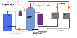
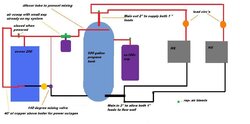
this is what i am building

  • Active since 1995, Hearth.com is THE place on the internet for free information and advice about wood stoves, pellet stoves and other energy saving equipment.

    We strive to provide opinions, articles, discussions and history related to Hearth Products and in a more general sense, energy issues.

    We promote the EFFICIENT, RESPONSIBLE, CLEAN and SAFE use of all fuels, whether renewable or fossil.
Status
Not open for further replies.

bowsky64x

New Member
Hearth Supporter
Sep 10, 2009
17
Thumb Michigan
Seems to make sense. whats your opinion
 

Attachments

  • vertical propane.jpg
    vertical propane.jpg
    46.1 KB · Views: 511
I hope it works well for you. It is a lot like the system Im building ,but I wont Know how well it works for at least a couple of weeks. Is your system all in one building ?
 
I'm pretty sure your circulator is on the wrong side of your boiler protection mixing valve
 
Ditto on the wood circ, it neds to be between the return protection valve and the boiler. Pipe size is not simple math: 1" + 1" < 2". 1 1/4 or 1 1/2 would be sufficient. I don't have the tables handy for flow rates but they are on the web. 100% wood, no backup?
 
yes, boiler circ needs to be between the mixing valve and the boiler. Also, you are not showing any gravity (power outage) dump zone. If you use a Temovar Loading Unit or a Laddomat Loading Unit you will most likely be able to thermosiphon to the tank in the event of a power outage. If you are using a mixing valve and separate pump as shown, you will want to put a gravity fed dump zone above the boiler. This is much less of a concern if you have an auto-start generator or battery UPS in case of power outage.

I don't know why your tees at the end of the the two 2" pipes coming out of your tank wouldn't work, but this kind of thing is normally referred to as "generously sized supply and return headers" and the zone piping comes into the large diameter header from the side. Anyone know if this matters for proper flow in an actual system, or is it just for pretty drawings?

Chris
 
Here's a flow rate chart. First you would need to match this to the HX size. What I think Chris is suggesting would be going for example 1.5" to first HX and then reducing to 1.25 to second HX all in one pipe run. You can see the large drop off in 1.25" to 1" BTU carrying capacity.
You could also get away with 1 large expansion tank. Possibly remove the smaller one and change the location of the 160 to the airvent location.
Where you have a air vent located on top of the storage tank it would be a good place to have a pressure relief valve. This can double as a air vent as well. If you do this you want a plain Pressure Relief not a Temp and Pressure like on boiler. We're looking for high temps. May not be the best idea if it's going to be sealed in a box or get insulation wet if it leaks, just a thought for extra safety.

Are there some other options where the storage tank is acting like a hydraulic separator ?
 

Attachments

  • 001.jpg
    001.jpg
    77.7 KB · Views: 359
One more reason to use a much larger header pipe size into your storage tank than is necessary is to slow the water down before it enters the tank so as to minimize turbulence and therefore help preserve the stratification of hot and colder water in the tank. I don't think too big is possible for that reason.
 
Tarm Sales Guy said:
Also, you are not showing any gravity (power outage) dump zone. If you use a Temovar Loading Unit or a Laddomat Loading Unit you will most likely be able to thermosiphon to the tank in the event of a power outage. If you are using a mixing valve and separate pump as shown, you will want to put a gravity fed dump zone above the boiler. This is much less of a concern if you have an auto-start generator or battery UPS in case of power outage.

Chris are you reffering to the idea that a "mixing valve" would normaly be powered by an electric actuator and therefore would stop working in a power outage?
So could you use a thermostatic mixing valve like the Danfoss ESBE and the boiler and tank plumbing were set up for thermosiphon then that would work also?
Thanks
Erik
 
thanks for the input. good call on pump location! I planned to add a overtemp loop but just didn't draw it.
As far as pipe size in tank bigger is better here regardless of a chart. the larger input will ensure good flow on out side and it will help to prevent mixing on input side.
Welding and pluming are no problems being I can do all of it myself. Due to the lack of people who know what they are doing in my area I am forced to do all this myself. i installed my econoburn last year myself using a series setup that flows water from my stove to my exchangers at all times the water temp is over 150 . wich is standard econo controll. I used the best guess method for sizing pipe and circs and exchanger size. it has worked awsome so far, no trouble heating my 1700 sq ft house and 1500 sq ft shop. My only problem is that I want to use my stove on the shoulder seasons and that requires storage. I wouldn't mind having 500 gallons of hot water on tap at all times anyway. For those of you who noticed the expansion is roughly twice the size needed but due to the small price difference between that and what I need I will just buy the bigger one in case i want to add another 500 gallon.
 

Attachments

  • vertical propane.jpg
    vertical propane.jpg
    51.4 KB · Views: 275
Status
Not open for further replies.