Updating solar system?

  • Active since 1995, Hearth.com is THE place on the internet for free information and advice about wood stoves, pellet stoves and other energy saving equipment.

    We strive to provide opinions, articles, discussions and history related to Hearth Products and in a more general sense, energy issues.

    We promote the EFFICIENT, RESPONSIBLE, CLEAN and SAFE use of all fuels, whether renewable or fossil.

begreen

Mooderator
Staff member
Nov 18, 2005
104,681
South Puget Sound, WA
We have an existing 2 array system. The original is field mounted and the second is on a tall pole. The pole mount has ten 270w Itek units (made in WA for discount) with a 2700 watt capacity and the original older array is composed of 15 Silicon Energy 195w panels. Design capacity 5,625 kW. The current inverter is a 10 yr old Aurora PowerOne 2 channel 4200w inverter. It's working fine but tops out at 4200watts which is less than the 2 arrays capacity.

Adding panels to the pole mount is not an option, however, it might be possible the field-mount array. Higher output could be achieved there though there is a caveat. Silicon Energy went bankrupt as panel failures started popping up. They are made from laminated tempered glass which can delaminate over time. They have also had issues recently cropping up with bypass diode failures which can lead to a fire. We have one panel that is starting to delaminate. We are trying to decide whether to limit liability by replacing the SE panels, but that would also mean a new inverter. Theoretically, we could boost system capacity to around 6.7kW and perhaps boost daily gains by addressing spring and fall shading issues on pole mount by a switch to microinverters. I will be getting a quote for options soon but would like to better understand the pluses and minuses of the options. Given that we were sold this system with a 20 yr warranty on the SE panels I am going to be pushing for a trade-in credit or at cost discount for the new hardware. We'll see. The company is a good one and I was one of their early customers.
 
Here are some more thoughts:

Do you ever intend on adding a battery to the system? If so that might narrow down the inverter options a lot.

As for temperatures, a ground mount array will stay much cooler than a roof mount, possibly reducing temperature based failure of a microinverter setup. Also allowing much easier inverter swaps, to the point many homeowners can perform this task.

For string inverter setups with optimizers, how confident would you feel that those components are available 15 years down the road if one fails? Brands aren't really interchangable in this configuration, so let's say a single optimizer in a Solaredge system fails, if the optimizers have been discontinued it renders the rest useless as well, of course you could just go back to a traditional string setup without optimizers, but now you have a lot of expensive paper weights. Same with the inverter, if that fails and is no longer available will the optimizers work with the new inverter, or do those need to be replaced as well? If a microinverter fails you may not be able to get the same model again, but you will be able to get another model that will work without replacing them all.

What I would do:

My parents have been looking at a ground mount array for their house, we have calculated that a 4kw system will meet 100% of their annual usage. We have been considering doing this as a DIY install. For this system we would likely go with 10 400watt bi-facial panels, and 3 APSystems QS1A (4 panel per inverter 1500 watt total) inverters (not available in the US, but the 1200watt QS1 is). This has been chosen for a few reasons:

1. Cost, as a DIYer we can get these 3 microinverters cheaper than any comparible output string inverter not including optimizers, adding optimizers makes the string inverters twice as expensive.

2. Modularity, there would be 2 extra connections on the last inverter to add another 800 watts of panels. As well it is very simple to add more capacity as demand grows, central AC and a plug in hybrid are likely in their future, and would likely push the system to 6kw or more. String inverters make this process much more complex and would likely require adding a second inverter for the additional capacity, further reducing the cost effectiveness.

3. Partial shade conditions, due to our cold temps and snow shading is an ever present problem in the winter, along with tree shading for a small percentage of the day, necessitating module level control, again pointing to microinverters due to cost.

4. Bi facial panels, we are strongly considering these if cost allows, there would be an appreciable gain to be had from the reflection of the snow in winter on the backside of the array, which would be a great benefit to the already low winter production.

5. Battery backup at present time isn't an option we want to consider, economically they don't pay back here, and they already have a portable generator to use during an outage. So with that said the lack of battery connectivity on the APSystems products isn't a concern.


I know I never really answered any of your questions, but wanted to give you more items to consider, and give a brief explanation to my thought process on a potential ground mounted array.
We have one 15 panel ground mounted array in the field and one pole mounted 10 panel array. The ground/field mount is all we are thinking of replacing. There's nothing on the house due to shading issues except in mid summer.
 
We have one 15 panel ground mounted array in the field and one pole mounted 10 panel array. The ground/field mount is all we are thinking of replacing. There's nothing on the house due to shading issues except in mid summer.

Personally I'd be doing 12 335ish watt panels, and 3 QS1 microinverters to replace that array. I would leave the pole mount on one channel of the existing Aurora inverter. That would give you 6.720kw of DC output and, 6.3kw of AC output. The new array would see minor clipping for an hour or two at peak output.

I know others will have different opinions on this, but for me would be the simplest, most cost effective way.
 
Given your circumstances new panels on the ground mount with multipanel microinverters makes a lot of sense.

Sad to hear the panels are failing prematurely, that is the big crap shot on solar, unless the panels havea third party warranty like Canadian Solar used to offer (not sure if they still do) we are all SOL if the company that made them goes out of business or sells off the liability. Knock on wood all my orphan panels (Evergreen, Shuco and Sharps)are humming along. I do have some Siemens (Solar Worlds) that are defective but well past 20 years). I would budget for a spare inverter and possibly a panel. It will not isolate you from poor design but may cover typical microinverter failure rates and a random rock.

I really wonder how much impact the bifacials will actually give but given that its a go around around the tariffs they are affordable.
 
Yes, the Silicon Energy company failure is a bummer. At the time, they were the only "made in WA" panels that got us on board with the best incentives back a decade ago. For 10 yrs we were paid 54¢/kWh and an additional 10¢/kWh for net metering. The panels were expensive and this helped with the ROI. We had only one issue up to now, a stone thrown by a weedeater shattered the back glass of one panel. No more weedeating near the panels now. The peak output has declined, perhaps due to the beginning delamination of one panel. When new, the array would put out around 2600w. Now it is about 2100.

We are fortunate that the installer is competent and conscientious. They have a stock of replacement panels should we decide to stick with them and just replace the failing panel. We need to do a cost-benefit analysis on the alternatives and decide if we want to boost output, consider islanding and battery backup. The bifacials would not be worth it for replacements here. We don't get snow very often and behind the field array is darker. I also would be leary of putting up more tempered glass laminated panels. One concern with microverters or islanding is that we are not setup for this. The arrays are 100 & 150' away from the house, and there is no signaling wiring in the conduit to the main panel.
 
Last edited:
There is no need for signal wiring for microinverters, the communication signals are interposed on the 240 VAC lines that carry the juice back. Most microinverters use proprietary trunk cables but once you are on the main run to the house you can put in a junction box and go with standard cable. What you cant fix is that string inverters operate at typically double the voltage so your home run cables in the conduit may be be too small to carry the higher current. If you have room you could pull in larger gauge wires or worse case is you need to replace the conduits(that s pretty rare).
 
I would have to look up the original specs, but IIRC correctly we went down an extra gauge for the run from the inverter to the house.
 
What you cant fix is that string inverters operate at typically double the voltage so your home run cables in the conduit may be be too small to carry the higher current. If you have room you could pull in larger gauge wires or worse case is you need to replace the conduits(that s pretty rare).

I'm a little confused with that statement, from what I've found all residential solar inverters operate on 240volt AC, what would change in regards to string vs micro inverters?
 
Sorry I assumed the string inverter is at the house rather than at the array. If the string inverter is at the array then you are right, its the same voltage and current as a microinverter based system. String inverter input is usually 300 to 500 volts DC with 240VAC out. Most folks if possible put their inverters in the house or in basement as its usually a more pleasant and secure environment. In that case the wires from the string to the string inverter are the DC voltages in the string. This allows smaller lower cost conductors from the array to the inverter as the same amount of power is being moved but at higher voltage the current is lower (DC power = DC voltage*DC amperage).

Ideally when the strings are calculated, the lowest temperature expected is used to calculate the maximum voltage for each panel, the number of panels in the string are then adjusted so that the voltages adds up to be just less than the maximum voltage rating of the inverter. Current is what causes heat in electronics so the highest voltage causes slightly higher efficiency.

BTW most wire used for PV is rated for 600Volts so using it for 240VAC is kind of a waste. Wire from commercial installations is rated for 1000Volts and strings can be run over 600 volts for commercial arrays.

I do have to talk generalities with design as every system can vary somewhat ;) If in doubt I default to best practice and my three systems,
 
Last edited:
Yes, the inverter is sheltered and mounted on the backside of the ground mount array superstructure. We have rural enforced security. Not visible from the road. 240v lines head to the house. We wanted to be able to plan for expansion, which we did in 2015 by using the second side of the inverter. This was earlier tech, the only microinverters were enPhase and they were not reliable enough for confidence. We were the 7th install in our community. There are over 200 now.
 
Last edited:
Sorry I assumed the string inverter is at the house rather than at the array. If the string inverter is at the array then you are right, its the same voltage and current as a microinverter based system. String inverter input is usually 300 to 500 volts DC with 240VAC out. Most folks if possible put their inverters in the house or in basement as its usually a more pleasant and secure environment. In that case the wires from the string to the string inverter are the DC voltages in the string. This allows smaller lower cost conductors from the array to the inverter as the same amount of power is being moved but at higher voltage the current is lower (DC power = DC voltage*DC amperage).

Ideally when the strings are calculated, the lowest temperature expected is used to calculate the maximum voltage for each panel, the number of panels in the string are then adjusted so that the voltages adds up to be just less than the maximum voltage rating of the inverter. Current is what causes heat in electronics so the highest voltage causes slightly higher efficiency.

BTW most wire used for PV is rated for 600Volts so using it for 240VAC is kind of a waste. Wire from commercial installations is rated for 1000Volts and strings can be run over 600 volts for commercial arrays.

I do have to talk generalities with design as every system can vary somewhat ;) If in doubt I default to best practice and my three systems,

That makes sense, that was the part I was missing, I had never considered running the DC power to a house mounted inverter.

Our electrical code creates added steps for transmitting DC power, for example DC shutdowns are required if the cabling extends more than 1 meter away from the array. Some of the rules are almost written to discourage higher voltage DC wiring in general, most of which don't apply below 50 volts DC, which again favors microinverters. Which I can understand, particularly when the wiring is live anytime the solar panels see sunlight, 600 volt DC isn't something I'd want to play with.
 
Given that your installer has access to replacement panels I would be tempted to try that route first, assuming the other panels are in good shape. Even if you only get a couple more years from the system it might be worth prolonging replacement of the entire array. Of course the unknown in this is what future incentives for solar could be along with component prices.
 
US has the same DC rule except for ground or poles mounts. That is what a RSD (Rapid Shutdown Device ) does. The last code cycle revised the language to make it more explicit. Anywhere else the RSDs are required.

Note some AHJs made this difficult by requiring them with interior mounted inverters. In that case folks went with the inverters t the array.
 
Given that your installer has access to replacement panels I would be tempted to try that route first, assuming the other panels are in good shape. Even if you only get a couple more years from the system it might be worth prolonging replacement of the entire array. Of course the unknown in this is what future incentives for solar could be along with component prices.
That may end up being the case, we'll see. Right now I am just assessing the options. The SE panels output is disappointing by today's standards. The 15 x 195w panels = 2925w. When new they would put out an actual 2600-2700 max. Now the output is more like 2000-2100w. By design they are supposed to still be putting out 80% and instead it's more like 76%. In that same ground mount rack it looks like I could boost the actual output capacity of the ground mount by 80% so it seems worth exploring.
 
There is no need for signal wiring for microinverters, the communication signals are interposed on the 240 VAC lines that carry the juice back.
Some microinverters (e.g., APsystems) are also featuring wireless communication like Zigbee. This was a consideration when I was adding 6 panels with microinverters to our 30-panel string inverter system. I did not like the idea of spending what EnPhase wants for their gateway and maybe depending upon an internet connection for PV monitoring.

I'm relying upon the microinverter indicator lights and a clamp-on amp meter to monitor individual panel performance for those so equipped.
 
That may end up being the case, we'll see. Right now I am just assessing the options. The SE panels output is disappointing by today's standards. The 15 x 195w panels = 2925w. When new they would put out an actual 2600-2700 max. Now the output is more like 2000-2100w. By design they are supposed to still be putting out 80% and instead it's more like 76%. In that same ground mount rack it looks like I could boost the actual output capacity of the ground mount by 80% so it seems worth exploring.

That's understandable, I can see where if you want to add more capacity anyway it makes sense to remove those panels and re-use the racking with new panels and inverters.

FWIW for me to buy 12 315watt Longi panels, 3 QS1 inverters, and the trunk cable I'm right at $4k CDN at retail prices, which works out to a 3.78KW system. So with exchange rate that's $3250ish USD.
 
Online monitoring is mostly a "scam" put in so that firms who do creative financing on systems can monitor the systems remotely. They are effectively renting the homeowners roof and selling the solar attributes and tax advantages to third parties and they need to remotely monitor the systems to do so.

If you have visual access to the microinverters, the Enphase's have a LED that blinks but its not particularly bright. Not an option on roof mounts but adequate for a pole mount or my wall mount. A ammeter and a Current Transformer is cheap to install on one of the leads prior to entering the main panel for continuous monitoring or overall output. There are various home energy monitors that can easily be be expanded to include the PV output.
 
There are various home energy monitors that can easily be be expanded to include the PV output.
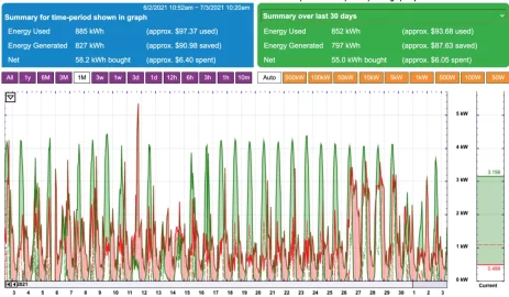
Yes, we have an eGuage system monitoring the solar output and whole house usage.

Screen Shot 2021-07-03 at 10.22.38 AM.png
 
I guess the grouchy old man part of me comes out when I see the added complexity that some of the systems have. My thoughts are keep if simple stupid (KISS). That added flexibility communicating out over the internet seems to be notoriously unreliable as the manufacturer seem to be perpetually sending out updates that upset the monitoring.
 
Agreed, I like KISS in my woodstove and solar, though our car is anything but KISS.

I have been monitoring the system on sunny days. What I now think I am seeing is that each of the two channels is clipping at around 2130 w. This would be to stay within the 4200w design capacity of the inverter, though I have seen it peak at 4500w occasionally. If this is the case, and the SE panels could actually be trying to put out more wattage, then theoretically I should have about an extra 1.9 kW of output potential between the two arrays. (Say 2600w from the SE array and ~2500 from the Itek array) This has me wondering about the least expensive option to achieve maximum output from the existing 2 arrays.
 
What is the nameplate rating and number of panels on each string?. Do you have single or multiple MPPT circuits.? IMHO, I always underload inverters instead of the industry tradition of overloading them and clipping them on the "good days" I think my approach puts a bit less stress on the electronics.

If you have 240VAC lines running back to the house with adequate ampacity how about installing a subpanel next to the inverters and cutting a few panels off each string, particularly ones that may get shade off the strings. You will need to rerun the inverter string calculations to make sure that you are still above the minimum string voltage for the inverter (lowest voltage is panel voltage multiplied by panel temp coefficient at highest anticipated temp). Then pick up some micro inverter trunk cables and install microinverters on those panels you cut out and tie them to the subpanel then send the combined outputs to the house via the existing cables. This off loads your inverters. Of course you then need to review the 20% rule for your main panel. The 20% rule is the panel can only be backfed 20% of the main buss bar rating. So if you have a 200 amp panel you can only hook up 40 amps of panels. So add up the nameplate wattage on the inverters, divide by 240 volts. 20% of 200 amps is 40 amps. So 40 amps multiplied by 240 volts equals 9600 watts so you should be covered. If you have a 100 AMP panel I think you would need to do a line side tap or a new panel unless you have an odd panel with higher amperage bus bar then the main breaker.

If you had asked a couple of months ago I would have suggested the surplus Solar City 6 K inverters that were on the market for cheap. Hard to beat at $500 each and hybrid to boot. I picked up one for spare. They were designed for an oddball Tesla battery for off grid that is no longer available but some folks are using them off grid with no battery without smoking them.
 
Agreed, I like KISS in my woodstove and solar, though our car is anything but KISS.

I have been monitoring the system on sunny days. What I now think I am seeing is that each of the two channels is clipping at around 2130 w. This would be to stay within the 4200w design capacity of the inverter, though I have seen it peak at 4500w occasionally. If this is the case, and the SE panels could actually be trying to put out more wattage, then theoretically I should have about an extra 1.9 kW of output potential between the two arrays. (Say 2600w from the SE array and ~2500 from the Itek array) This has me wondering about the least expensive option to achieve maximum output from the existing 2 arrays.

That's easy to test. If this is the correct manual for your inverter, and the correct specs for you panels, the inverter can have up to 3000 watts per MPPT channel to a maximum of 16 amps DC. By math both your SE and Itek panel strings have voltages over 300V at Vmp, so the 16 amp spec isn't the limiting factor, the max 3000 watts per channel is. The other interesting thing is that your inverter should actually be capable of 4600 watts output total if it is connected to 240 volt AC and not experiencing thermal derating (happens above 40c).

Simply unplug or disconnect one array at a time and then monitor the output of the other, this will reveal what each array is capable of and will determine if the inverter is experiencing significant clipping, or if it is the panels limiting output.

Will check this tomorrow when the sun returns.