One wire temp sensor Accuracy and Calibration Questions for my GARN sensor network.

  • Active since 1995, Hearth.com is THE place on the internet for free information and advice about wood stoves, pellet stoves and other energy saving equipment.

    We strive to provide opinions, articles, discussions and history related to Hearth Products and in a more general sense, energy issues.

    We promote the EFFICIENT, RESPONSIBLE, CLEAN and SAFE use of all fuels, whether renewable or fossil.
Status
Not open for further replies.

deerhntr

Member
Hearth Supporter
Mar 25, 2009
129
Kutztown.PA
Good Morning,

I finally got my one-wire temp sensor network up and running. Currently my network is about 175' with 5 sensors and I am monitoring my My GARN Water Temp, and the house circuit supply and return in the GARN Barn. I also have 2 extra sensors I set up for debug. I'm using the Dallas DS18B20 sensors. My questions are to those of you who have been through the "one wire sensor" data logger projects, or anyone with thoughts on accurate temperature measurement.

I have the standard dial thermometer in a well on the face of our GARN. I also installed a thermowell next to that thermometer for my one-wire sensor. I have a consistent offset between the thermometer and well sensor of about 6°F (the onewire sensor reads 6 °F lower). I then have senors on my supply and return pex. Those sensors are on the pex pipe, under 2" fiberglass pipe insulation, with no thermal grease, simply wrap tied to the pipes. My supply sensor consistently reads a 16 °F Offset from the Thermometer. The return of course varies it's value, and I have no reference to compare. I placed my debug sensor on a copper supply pipe, and found I could decrease the offset relative to the thermometer by about 4 °F .

So, my Questions:

1) Has anyone experienced this type of calibration issue, and what have you done to solve you problem?
2)Should I just accept the 6 °F well to thermometer offset, the 12 °F pipe to thermometer offset, and then just calibrate it out of my measurements, and be done with it?
3)What is the best way to attach one-wire sensors to copper and pex pipes?

My guess, this might be a re-hash for some, but new for me. Any help would be greatly appreciated. :)
 
I think pex is hard to get a good temp reading on. I had borrowed a insterment that had a pipe clamp temp sensor in it and I got different temp readings from my pex than my iron pipe.


Rob
 
I had similar issues and simply callibrated it in my code to compensate. I have one in a well that was only off from my other digital thermometer by I think about 3*. The one strapped on a copper pipe was off by more I think. Just compensate as best you can. If the sensor was directly in the water (not that it is possible) I think they would be right on. However, even a well will be off by a little just by its nature.

For on pipe sensing I used aluminum tape to attach it and covered it with pipe insulation. You can see my arduino project write up at both my new and old sites. I hope that helps a little.

deerhntr - Can I put a link to your Garn blog on my sites link page?
 
I have the same issue with my one wire sensors as well. I multiple the results from my boiler output temp by 1.1 and that gets me pretty close to the actual temperature most of the time. Its not very accurate if the temp drops really low but when the boiler is burning it works out fine.
 
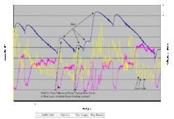
Attached is a plot of two days worth of data. I shows a few burn cycles, and the difference temps of the well-cu supply to the house, and the pex supply - pex return. The plot is interesting i the offset(well-cu pipe) changes over time. Now I would expect that since it is on the load side of the pump. But the smallest offset comes during a burn cycle. I may be wrong, but what I think it shows is significant heating of one,or both sensors during a burn. I know the thumbnail looks goofed up, but if you click the image, the full size should show the plot.
 

Attachments

  • image003.gif
    image003.gif
    26.7 KB · Views: 733
It is often the case that heat can travel along the copper leads.

For grins you might try getting a fold or two of lead wire inside the well, or fold/wrap the lead past the sensor under the insulation in the case of pipe surface mount.
 
WoodNotOil said:
I had similar issues and simply callibrated it in my code to compensate. I have one in a well that was only off from my other digital thermometer by I think about 3*. The one strapped on a copper pipe was off by more I think. Just compensate as best you can. If the sensor was directly in the water (not that it is possible) I think they would be right on. However, even a well will be off by a little just by its nature.

Yes, I think the cal constant is the way to go, provided you can come up with one. Take a look at the plot I generated in my previous post.

WoodNotOil said:
For on pipe sensing I used aluminum tape to attach it and covered it with pipe insulation. You can see my arduino project write up at both my new and old sites. I hope that helps a little.
That is a good idea. I also ordered some thermal grease to make better thermal contact.

WoodNotOil said:
deerhntr - Can I put a link to your Garn blog on my sites link page?
Sure, no problem. I haven't updated lately. It is about time. I wanted to get my data logger up in running so I could better debug the system.
 
I wrapped the end of the sensor with a little aluminum foil to make sure that there was enough contact area in the well. The sensor was thinner than the well opening... just a thought...
 
WoodNotOil said:
I wrapped the end of the sensor with a little tinfoil to make sure that there was enough contact area in the well. The sensor was thinner than the well opening... just a thought...

I tried that yesterday. Maybe one degree closer. I think am getting significant heat loss from the front of my unit that corrupts the values. I HAVE NOT insulated the front of my GARN as of yet, so I know my losses there are real. I didn't realize how much until now. I think until I have a better handle on minimizing that loss, my sensors will have this "variable error".
 
They do read low. Note all the users see low readings never any high ones.

I was able to get my boiler temp measure to be within 2 degrees by messing with it, one would think that a well insulated device would reach the temperature to be measured, but not so.

I have six inches of insulation over my sensors with the the package touching the piping.


Don't know how you are building yours but I found a small proto board (just enough for three rows and about 1 cm long helped me keep all the parts compact without a chance of shorting. I put the flat side up so I can install that side against the pipe or tank. I do have one layer of heat shrink over the parts, so that does insulate the case.
 
I plumbed everything to facilitate thermo wells but even that sounds like that doesn't matter. Will post my results when I get it going. The accuracy is supposed to be +/- 0.5 degrees. Is everyoe using the TO-92 3 pin or 8 pin SO chip? What about the quicksilver or thermopaste that goes between a CPU and a heatsink?
 
Three pin.

A passive device should not need heat sink compound. But we can't all be wrong. Even though the device draws very little current it must be enough to cause this problem. I suppose one of use could do a liquid submersion comparison, between a temperature meter and one of these devices.
 
sgschwend said:
Three pin.

A passive device should not need heat sink compound. But we can't all be wrong. Even though the device draws very little current it must be enough to cause this problem. I suppose one of use could do a liquid submersion comparison, between a temperature meter and one of these devices.

The DS18B20 is not a passive device. It has an A/D converter, and other active support circuitry. This is not a thermocouple. I believe the device is accurate, in fact very accurate. I feel the issue is coupling the temperature to the device. We are trying to sense the water temp through a pipe, cooper, black steel, or pex. There is lies the problem. A good and consistent thermal connection between the measuring device and the medium. Actually, I think the thermowells will provide the best chance for accurate measurement. I have ordered some thermal paste and will try to see if I can improve my measurements. I think the paste will help the device conform to the round surface, and hopefully minimize error. It may be futile, but time will tell.
 
Yes, I know it is not a passive device but they do advertise it as a device that can run on parasitic current, pretty close to passive.

Try this, put your device on a long cable say 25' and then set it in boiling water and check this value against a different type of measurement device. I hope they track and measure the same. But I fear the long cable will cause a low reading.

By insulating the area around the probes we should have little trouble keeping all of that space at the same temperature. The air around the probe should match the temperature around the pipe, if heat flow away from the pipe is kept very small the surrounding area will be the same temp, hence the probe should read the pipe temp.

It would be great if you find the heat sink compound makes an improvement.

I will try the same measurements and changes to see if we can find something too.

I was just living with the errors, my shortest cable has the lowest error my longest has the highest error; which may just be dumb luck.
 
sgschwend said:
Yes, I know it is not a passive device but they do advertise it as a device that can run on parasitic current, pretty close to passive.

Try this, put your device on a long cable say 25' and then set it in boiling water and check this value against a different type of measurement device. I hope they track and measure the same. But I fear the long cable will cause a low reading.

By insulating the area around the probes we should have little trouble keeping all of that space at the same temperature. The air around the probe should match the temperature around the pipe, if heat flow away from the pipe is kept very small the surrounding area will be the same temp, hence the probe should read the pipe temp.

It would be great if you find the heat sink compound makes an improvement.

I will try the same measurements and changes to see if we can find something too.

I was just living with the errors, my shortest cable has the lowest error my longest has the highest error; which may just be dumb luck.

The signal that a DOW chip puts out is digital, not analog - cable length should have NO effect on it, so long as the signal can get through... I would try a couple of sensors just to make sure they are consistent, I would also say that the heat-sink compound is CRITICAL - not to cool the chip, but to ensure that the temperature is actually reaching the part - which should also be clamped securely to the item being measured and insulated on all other surfaces... Also the leads should be heat shrunk, or otherwise protected against shorts, the device itself should NOT be, unless trying to waterproof it. - remember heat shrink is also thermal insulation...

I have seen a couple of places that say that while some of the DOW devices can run off "parasitic power", they will work better if that third wire is connected to a power source (It doesn't take much of one)

Gooserider
 
G. The device does have an analog component, yes the transmission of the data is digital. There are many ways that an analog device can be fooled by noise or error signals. Why my longer cables have more error is a mystery that is why I called it dumb luck.

I have produced probes with the leads captured in a epoxy mold and also using a small piece of proto board. The proto board works better.

I have also had two probes fail after a few hours inserted into the boiler tube. Located right next to a thermistor prob which had no problem with the location. I really liked th tube because there is so much surface area and the opened can be insulated to hold the hot air.


I think this device was some sort of MOS technology, CMOS? If so the C stands for complementary, which I believe referred to the current needed to switch, the topology was setup so that the upper switch transistors would alternate the current with the lower switching transistors so that the current would alternate having a net zero current change while the switch output was changing. All very high impedance, much more susceptible to stray energy.

I was surprised to see my devices show up in a clear plastic bag, perhaps I am too old but I don't recall an ESD label on the bag or the paperwork.
 
OK, used some heat sink compound on two of my probes.

The first was a measurement at the top of the boiler, the thermistor is measuring the same temperature near there. There use to be a 2-3 degree error, but with the goop the error is now gone. The two probes even track within a .1 degree of each other.

The other two probes are on my storage tank and there isn't an easy way to verify, I will try a hand held and a non contact. In both locations I am not sure I saw any change. For example: the boiler was putting out 156F and the top of the tank was reading 145F.

What do you think? It looks to me that the goop is necessary.
 
sgschwend said:
OK, used some heat sink compound on two of my probes.

The first was a measurement at the top of the boiler, the thermistor is measuring the same temperature near there. There use to be a 2-3 degree error, but with the goop the error is now gone. The two probes even track within a .1 degree of each other.

The other two probes are on my storage tank and there isn't an easy way to verify, I will try a hand held and a non contact. In both locations I am not sure I saw any change. For example: the boiler was putting out 156F and the top of the tank was reading 145F.

What do you think? It looks to me that the goop is necessary.

Sounds good!

I got my thermal goop today, but is was real nice here in PA. and I had to work on next years wood supply. I am going to test it out tomorrow.

My gut feeling was the thermal grease would help. I was planning on running two sensors side by side, one with the grease, one without. I have been searching the net for other folks experience, and the consensus is the DS18B20 measure low, and thermal grease or epoxy does help. The difficulty is getting good thermal conduction to the package.
 
All,

I don't have any of these probes, but for what its worth here is my thought on why everyone is reading lower temperatures. I suspect the sensors are being cooled by the lead wires. I have quite a bit of experience measuring temperature of electronics using thermocouples. Even with fine wire (say 30 ga or so), the wire will act as a heat sink for an electronic component. As Steve said, everyone is reading low when compared to a neighboring measurement. Also, the thermal grease eliminated the error in at least 1 case. Even with the sensor attached to a pipe and insulated, a thermal drain on the sensor will drop the sensor temperature if there is heat being conducted away from the sensor by the lead wires. A few thousandths of an inch of air between the sensor and the pipe may be all it takes to skew the measurements. This offset should become even worse when the sensor is attached to a pipe like PEX which has more thermal resistance than copper or iron. Finally, as noted by others here, the temperature error will change with the temperature to be measured. This is due to a change in the temperature difference between the sensor and the ambient air around the lead wires. As this sensor temperature and ambient temperature move closer together, you will have less error. So, cancelling the error by adding a constant factor will work over a narrow temperature range, but will not be accurate over wide temperature swings.

You may be able to overcome some of the error by wrapping a length of wire around the pipe, the length will depend on wire gage and insulation. The theory is with enough wire with the sensor inside the insulation, the heat transfer from the sensor will be decreased. However, in some cases the wire may be able to sink some heat away from the general location of the sensor. This is probably not an issue unless you are trying to measure water temperature through a thermal insulator (like PEX) or are measuring a location where there is no water flow.

You may be able to cancel the error using an error cancellation based on the ambient and sensed temperatures. This is just a wild thought, but it may be possible to measure the difference between the sensor and actual temperature at a number of different points and create an equation to remove the error based on sensor temperature and ambient temperature. I've done similar things with temperature measurements that were affected by setup or measurement location, I know it's possible to get an accurate measurement by "subtracting" the environmental affects of a measurement system from the measured results.

Just my 2c.

Good luck

Eric
 
RowCropRenegade said:
Really cool, Russ. Are you using the sensors for watching the system or for data tracking, maybe both?

Reed,
All the above, and system debug and optimization as well. This is all preliminary as of now. I am just getting my sensors up and running and the kinks worked out. Ultimately though I plan to track the data along with outside temps, relay closures and other pertinent info. Maybe even a web server for remote monitoring.
 
dirttracker said:
All,

I don't have any of these probes, but for what its worth here is my thought on why everyone is reading lower temperatures. I suspect the sensors are being cooled by the lead wires. I have quite a bit of experience measuring temperature of electronics using thermocouples. Even with fine wire (say 30 ga or so), the wire will act as a heat sink for an electronic component. As Steve said, everyone is reading low when compared to a neighboring measurement. Also, the thermal grease eliminated the error in at least 1 case. Even with the sensor attached to a pipe and insulated, a thermal drain on the sensor will drop the sensor temperature if there is heat being conducted away from the sensor by the lead wires. A few thousandths of an inch of air between the sensor and the pipe may be all it takes to skew the measurements. This offset should become even worse when the sensor is attached to a pipe like PEX which has more thermal resistance than copper or iron. Finally, as noted by others here, the temperature error will change with the temperature to be measured. This is due to a change in the temperature difference between the sensor and the ambient air around the lead wires. As this sensor temperature and ambient temperature move closer together, you will have less error. So, cancelling the error by adding a constant factor will work over a narrow temperature range, but will not be accurate over wide temperature swings.

You may be able to overcome some of the error by wrapping a length of wire around the pipe, the length will depend on wire gage and insulation. The theory is with enough wire with the sensor inside the insulation, the heat transfer from the sensor will be decreased. However, in some cases the wire may be able to sink some heat away from the general location of the sensor. This is probably not an issue unless you are trying to measure water temperature through a thermal insulator (like PEX) or are measuring a location where there is no water flow.

You may be able to cancel the error using an error cancellation based on the ambient and sensed temperatures. This is just a wild thought, but it may be possible to measure the difference between the sensor and actual temperature at a number of different points and create an equation to remove the error based on sensor temperature and ambient temperature. I've done similar things with temperature measurements that were affected by setup or measurement location, I know it's possible to get an accurate measurement by "subtracting" the environmental affects of a measurement system from the measured results.

Just my 2c.

Good luck

Eric

Eric

I agree with your analysis 100%. I was coming to a similar conclusion with other stuff I have read on the web, and a couple of experiments I have run the past couple of days.

As for calibrating out the error, I think that is a fair way to go. All the sensors would need to be constructed the same way, attached the same way, and then I should be able to come up with a simple "fit to the data" equation. The only problem would be controlling the "source" temperature accurately to generate the data set. I also in another life have some experience with characterizing electronics in temp controlled ovens. It was very easy in that lab environment to come up with some "cal constants", so I am very familiar with the exercise In my Garn Barn it may be a little more difficult to control all the variables. I am giving it some thought.

Thanks for the input! ;-)
 
While I agree with Eric's analysis, I don't know how much effort it is worth to try totally eliminating the error... Certainly use thermal grease / epoxy, and take other such mechanical steps to eliminate the error (side note, if using goops on a sensor attached to PEX, make sure it's chemically compatible...) However I don't know that "exact" values are necessary for monitoring or control purposes, as all that really matters is knowing what is "normal" and seeing differences from that...

No need to get micrometer accuracy on a yardstick grade measurement...

Gooserider
 
Gooserider said:
No need to get micrometer accuracy on a yardstick grade measurement...


Gooserider

While I don't completely disagree. I'm not sure I am trying to get 6 orders of magnitude improvement in measurement accuracy(1m = 10^^6 um). I would just like to have an accurate baseline so that I can determine if my system is working as it should.

I have not fully disclosed in this thread, but I believe I have some system loss that is causing me to burn more fuel that required. So as an aside from setting up a general data logger, I wanted to use the results to help me determine where I'm losing BTUs, and where best to concentrate my debug efforts. So, with that said I wanted to make sure my data was as good as I good make it. I am sorry if my questions seem to fine grained for the application.
 
Is there a way to have a data logger adjust the values your sensors are tracking? Say for example, the sensors are off 7 degrees in 180 water, netting 173. Or 150 degree water its off 5 degrees. The sensor data sends the data back to the computer, the program references to a % error chart and records the correct temperature. Not an exact science but plus or minus a degree or two seems "good enough"? Just some food for thought. I would think Microsoft Excel/Access could handle the conversion/tracking easily.
 
Status
Not open for further replies.